
Jetter cup holder

Inactive Publication Date: 2006-06-29
RUCKS CHAD
View PDF17 Cites 0 Cited by
  • Summary
  • Abstract
  • Description
  • Claims
  • Application Information

AI Technical Summary

Benefits of technology

[0008] The invention overcomes the disadvantages noted above by providing a jetter cup holder that retains a jetter cup without reliance on vacuum and prevents contamination. To that end, an embodiment configured according to principles of the invention for an apparatus includes a peg having a first portion, a second portion and a third portion interposed between and larger than the first portion and the second portion, wherein the third portion is larger than the opening of the jetter cup.
[0009] The invention provides improved elements and arrangements thereof, for the purposes described, which are inexpensive, dependable and effective in accomplishing intended purposes of the invention.

Problems solved by technology

However, typical jetter cup storage units are difficult to use and easily damaged.
This often leads to improper storing of the jetter-cups, thus defeating the purpose of the protective hood.

Method used


Image

  • Jetter cup holder
  • Jetter cup holder
  • Jetter cup holder

Examples


Embodiment Construction

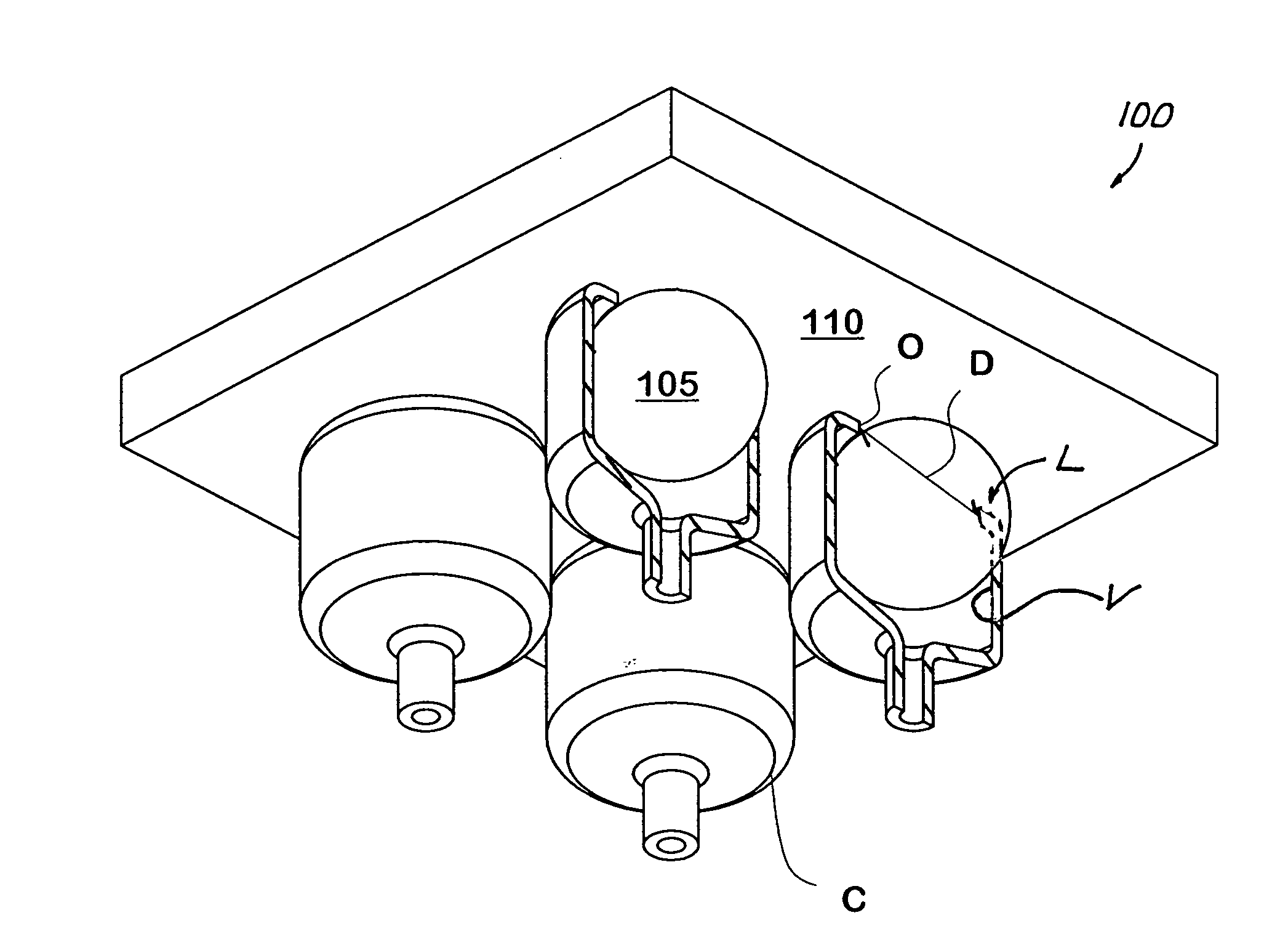
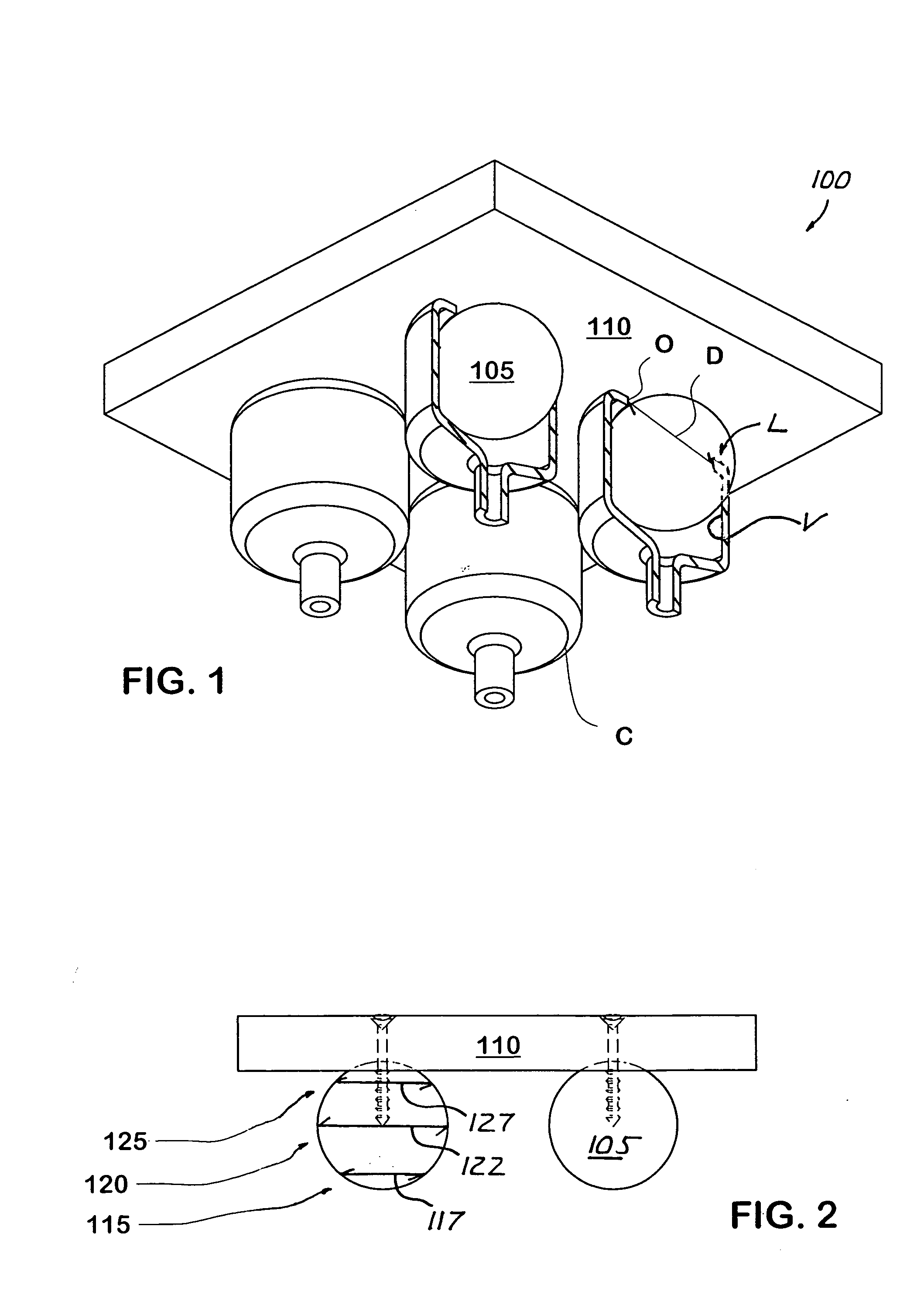
[0016] Referring to FIGS. 1 and 2, an embodiment configured according to principles of the invention is a jetter cup holder 100 that retains a jetter cup C without reliance on vacuum and prevents contamination. Jetter cup holder 100 includes a plurality of pegs 105, each configured to received a jetter cup C, mounted on a plate 110.

[0017] Each jetter cup C generally describes an open-ended volume V configured to receive the enlarged end portion of a milking cup (not shown) and having an inwardly disposed lip L. Lip L defines an opening O having a diameter D sized and configured to stretch for receiving the milking cup (not shown), then form an interference fit with the milking cup (not shown) once received. Once the milking cup (not shown) is cleaned, the milking cup (not shown) is removed from jetter cup C and jetter cup C is stored on jetter cup holder 100, as shown in FIG. 1.

[0018] Accordingly, referring to FIG. 2, peg 105 of jetter cup holder 100 is configured to receive and m...


PUM


Abstract

Apparatus for holding a jetter cup having an opening, includes a peg having a first portion, a second portion and a third portion interposed between and larger than the first portion and the second portion, wherein the third portion is larger than the opening of the jetter cup.

Description

BACKGROUND OF THE INVENTION [0001] Most commercial dairy farms use automatic milking equipment to milk cows, goats or other dairy animals. Such milking equipment typically includes a plurality of milking cups connected to a milking claw. The milking claw is connected to a milk collection receptacle via conventional flexible tubing. [0002] The milking cups typically include a rubber liner received within a shell. Milking cup liners have various configurations, but commonly include an enlarged mouthpiece extending around the top of the shell, a liner barrel within the shell, and a short milk tube that extends from the bottom of the shell to the milking claw. [0003] Automatic milking equipment typically cycles the pressure between the liner and the shell between negative and atmospheric pressure. The alternating pressure cycles cause the walls of the liner to massage and milk the teats of the udder. Continuous vacuum applied to the interior of the rubber liner moves the milk from the t...

Claims


Application Information

Patent Timeline
IPC IPC(8): A01K7/00
CPCA01J7/025
Inventor RUCKS, CHAD
Owner RUCKS CHAD
Learn More