
Optical encoder

Inactive Publication Date: 2006-06-29
LITE ON TECH CORP
View PDF9 Cites 2 Cited by
  • Summary
  • Abstract
  • Description
  • Claims
  • Application Information

AI Technical Summary

Benefits of technology

[0010] According to the invention, the precision of feedback control of the disclosed optical encoder is increased using the reflection difference between different rows of light-sensing cells.
[0011] According to the invention, multiple detections are made simultaneously to increase the reliability of detected signals of the disclosed optical encoder.
[0012] According to the invention, the errors, which are caused by the dirt on the code strip, e.g. a code wheel or optical scale, of the disclosed optical encoder are reduced.

Problems solved by technology

The resolution is thus limited and the device cannot be made too thin.
However, this is likely to increase the thickness of the optical encoder, contrary to the trend of miniaturization.
Moreover, errors occur when the code wheel is dirty.

Method used


Image

  • Optical encoder
  • Optical encoder
  • Optical encoder

Examples


Embodiment Construction

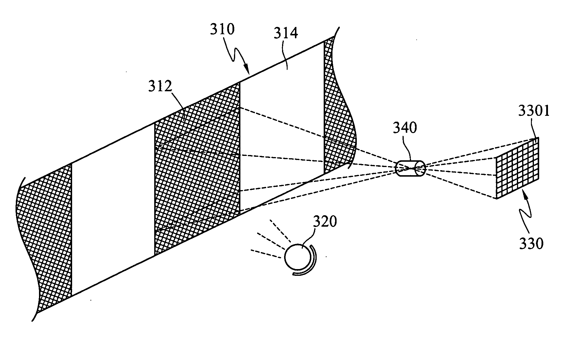
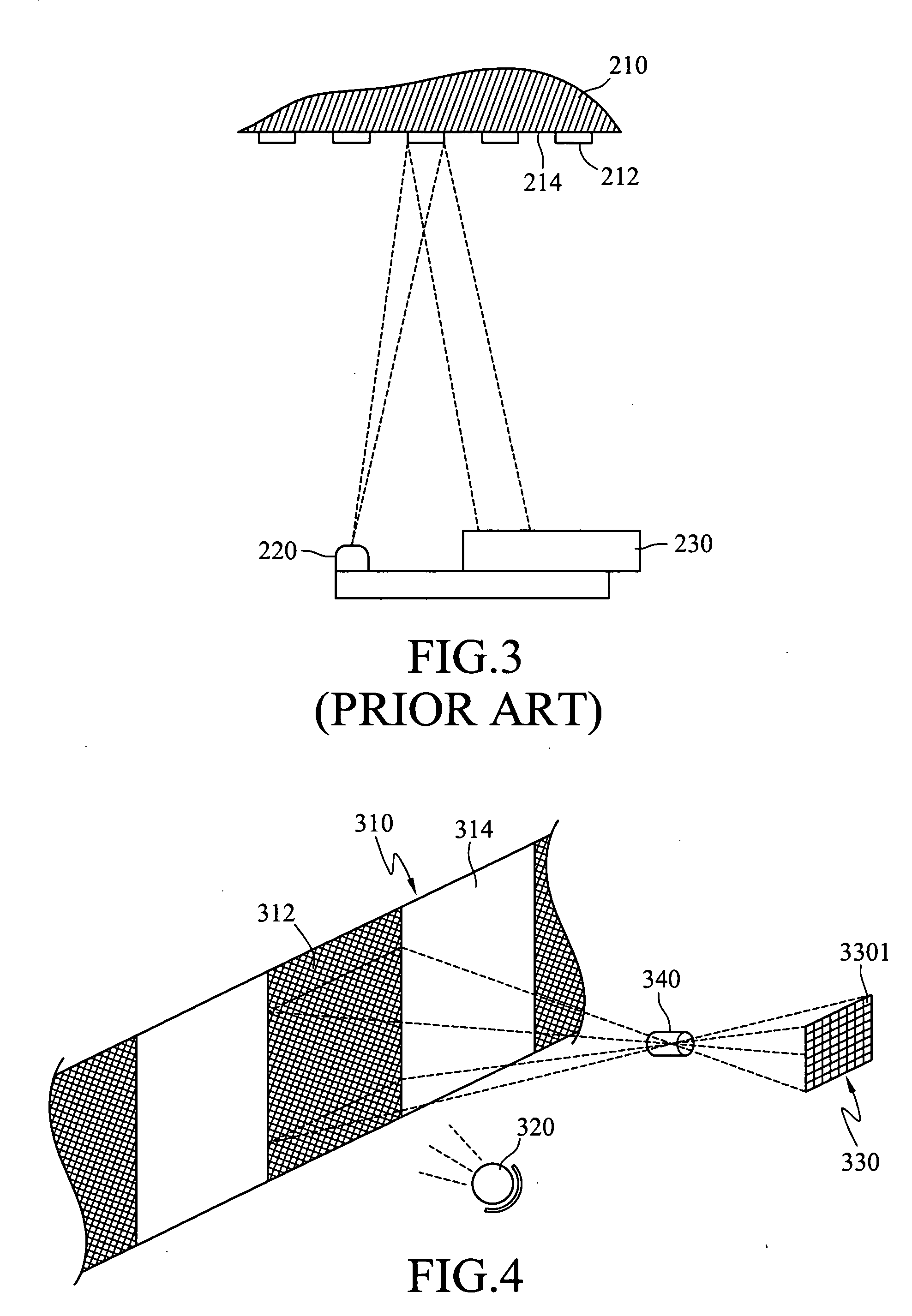
[0031] With reference to FIG. 4, an embodiment of the optical detector comprises: a code strip 310, a light source 320, a light sensing element 330, and a first lens set 340.

[0032] The code strip 310 is driven by a wheel (not shown) in response to the rotating device. It has reflective regions 312 and non-reflective regions 314 which are staggered. The code strip 310 is such as a code wheel or an optical scale.

[0033] The light source 320 emits light to illuminate the reflective regions 312 on the code strip 310. The light source 320 is such as an LED illuminator.

[0034] The light sensing element 330 disposed on the same side of the code strip 310 as the light source 320 receives the modulated light beam reflected by the reflective regions 312 and converts it into an electrical signal, thereby producing a binary identification code to determine the location of the rotating device for controlling the speed and stroke of the rotating device.

[0035] The light detecting element 330 has...


PUM


Abstract

An optical encoder is disclosed, in particular, which has a light sensing element with light-sensing cells arranged in a matrix. The light sensing element repeatedly detects the same reflective light beam by different rows of light-sensing cells to increase the precision of feedback control. Furthermore, since the light sensing element synchronously and repeatedly receives the reflective light beam, the reliability of detected signals is increased.

Description

BACKGROUND [0001] 1. Field of Invention [0002] The invention relates to an optical encoder and, in particular, to one having a light sensing element with light-sensing cells arranged in a matrix, thereby increasing its precision and reliability. [0003] 2. Related Art [0004] When detecting the location of a rotating device (e.g. a motor or a machine axis) or a high-speed moving device, one usually generates a binary identification code in response to each location of the detected device by the on and off of a detecting element in an optical or magnetic ways. For example, several typical optical encoders taught in the U.S. Pat. Nos. 4,451,731, 4,691,101, 4,952,799, and 5,317,149. [0005] These encoders mainly include: a light source for emitting light, a code strip for modulating the light in response to the operation of the rotating device, such as a code wheel, an optical grating disk, or an optical scale, and a photo detector for receiving and detecting the modulated light beam. In ...

Claims


Application Information

Patent Timeline
IPC IPC(8): G06K7/10
CPCG06K7/10683G06K7/14
Inventor WEI, CHIH-HSIEN
Owner LITE ON TECH CORP
Learn More