Ink jet recording apparatus

a liquid jet and recording apparatus technology, applied in the direction of printing, inking apparatus, etc., can solve the problems of unstable discharge operation, insufficient supply of ink to the discharge ports, and increase the density of images, so as to reduce the effect of the discharge ports and the temperature distribution of the head

Inactive Publication Date: 2006-06-29
CANON KK
View PDF7 Cites 70 Cited by
  • Summary
  • Abstract
  • Description
  • Claims
  • Application Information

AI Technical Summary

Benefits of technology

[0047] As described above, according to the present invention, advantageous effects as described below can be obtained.
[0048] Ink can flow from the liquid reserve tank into the in-substrate liquid path provided in the base substrate of the liquid jet head even while the liquid jet head is currently carrying out the liquid jet operation.
[0049] In addition, a liquid jet recording apparatus can be provided that is capable of reducing a rise in the temperature of the head and a temperature distribution in the head even if continuous printing is carried out with a long full-line type head.
[0050] In addition, ink can flow from the sub-tank into the head liquid chamber provided in a head liquid chamber member that is provided as a supply path for ink for printing.
[0051] Thus, it is possible to alleviate the effect on the discharge ports caused by fluctuation in the liquid level of a main tank with a great head difference with respect to an ink discharge section. Accordingly, a liquid jet recording apparatus can be provided that is capable of printing a high-quality image by stably supplying ink to the head.
[0052] Further features of the present invention will become apparent from the following detailed description of exemplary embodiments with reference to the attached drawings.

Problems solved by technology

Therefore, there is a problem such that in this case, the density of an image is gradually increased.
Then, the separated-out air is accumulated, and as a result, the ink is not supplied to the discharge ports in a sufficient amount.
Thus, there occurs phenomena of an instability of a discharge operation and a discharge failure in the worst case.
However, there is a problem such that it is impossible to decrease the number of ink discharge nozzles used at the same time to a submultiple of the number of nozzles by carrying out the image formation by distributing the operation into multiple passes as in the case of a serial type recording apparatus that forms an image by reciprocating movement of the head.
Thus, there is a problem such that the temperature distribution is caused in the same head, and the printing density becomes uneven.
In a case where a continuous printing at a high resolution is carried out by a full multihead, the ink supply for offsetting the rise in the temperature cannot be implemented, and it is not possible to carry out a sufficient cooling of the head.
Therefore, the recording apparatus of this type is liable to be directly affected by the fluctuation of a head difference between the liquid levels of the ink cartridge 3 and an ink discharge section.
That is, in a case where continuous printing is carried out by a liquid jet recording apparatus using a full-line type liquid jet head capable of high speed printing, there is a problem such that a capacity of cooling the head is not high enough.

Method used


Image

  • Ink jet recording apparatus
  • Ink jet recording apparatus
  • Ink jet recording apparatus

Examples


first embodiment

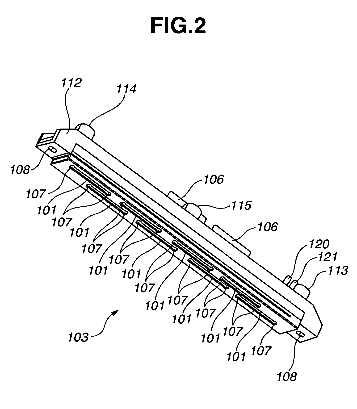
[0078] To begin with, a head configuration of a liquid jet recording apparatus according to a first embodiment of the present invention is described with reference to FIG. 2 through FIG. 7.

[0079]FIG. 2 and FIG. 3 are perspective views showing an ink jet head viewed from the side of a head substrate element and viewed from the side of a liquid supply port, respectively. FIG. 4 and FIG. 5 are views explaining a detailed structure of a base substrate of the head, respectively. FIG. 6A is a front view showing the ink jet head according to the first embodiment of the present invention when viewed from the side of a liquid supply port. FIG. 6B is a cross sectional view taken along line 6B-6B of FIG. 6A. FIG. 6C is a front view showing the ink jet head according to the first embodiment of the present invention when viewed from the side of a liquid discharge port. FIG. 6D is a cross sectional view taken along line 6D-6D of FIG. 6C. FIG. 7 is a side cross sectional view showing the details ...

second embodiment

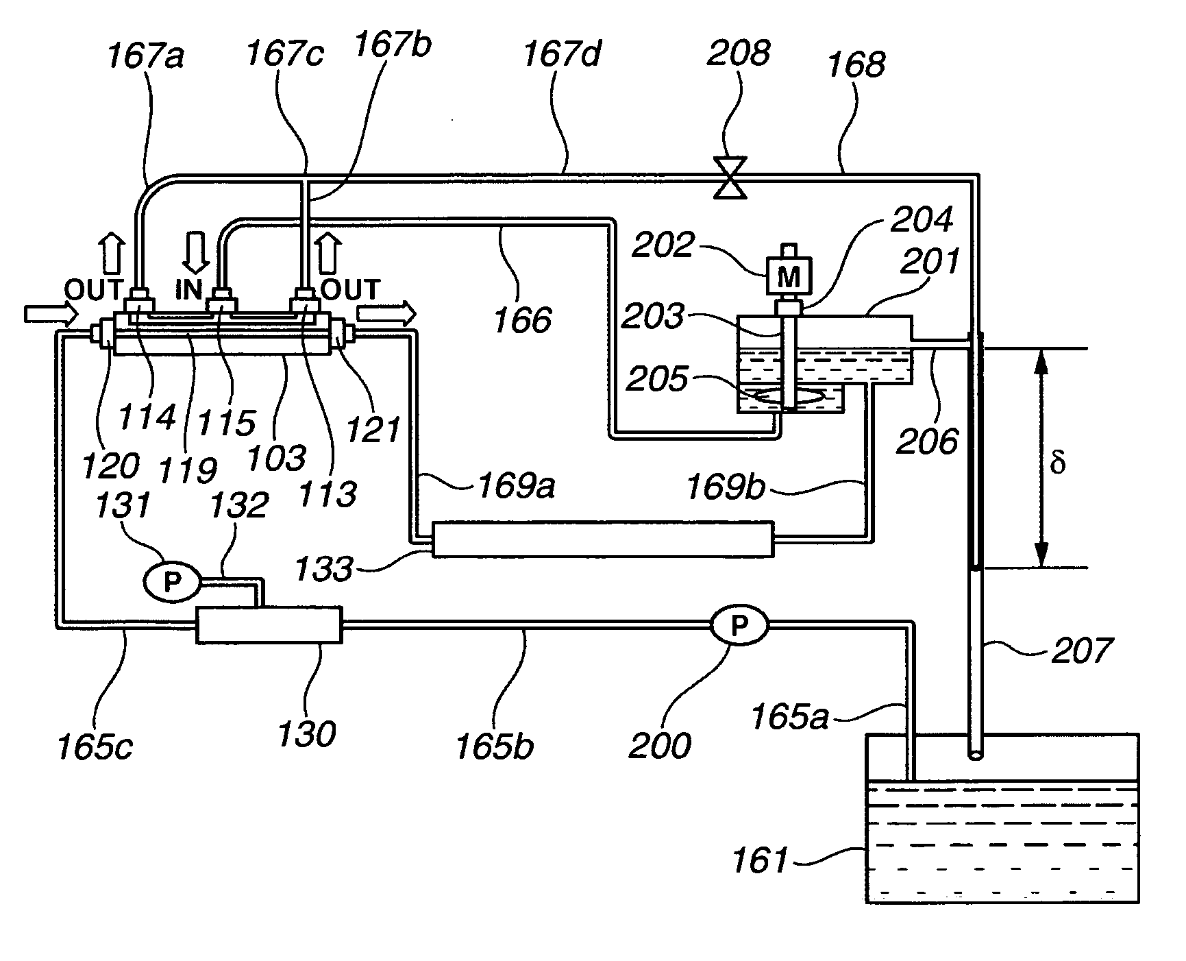
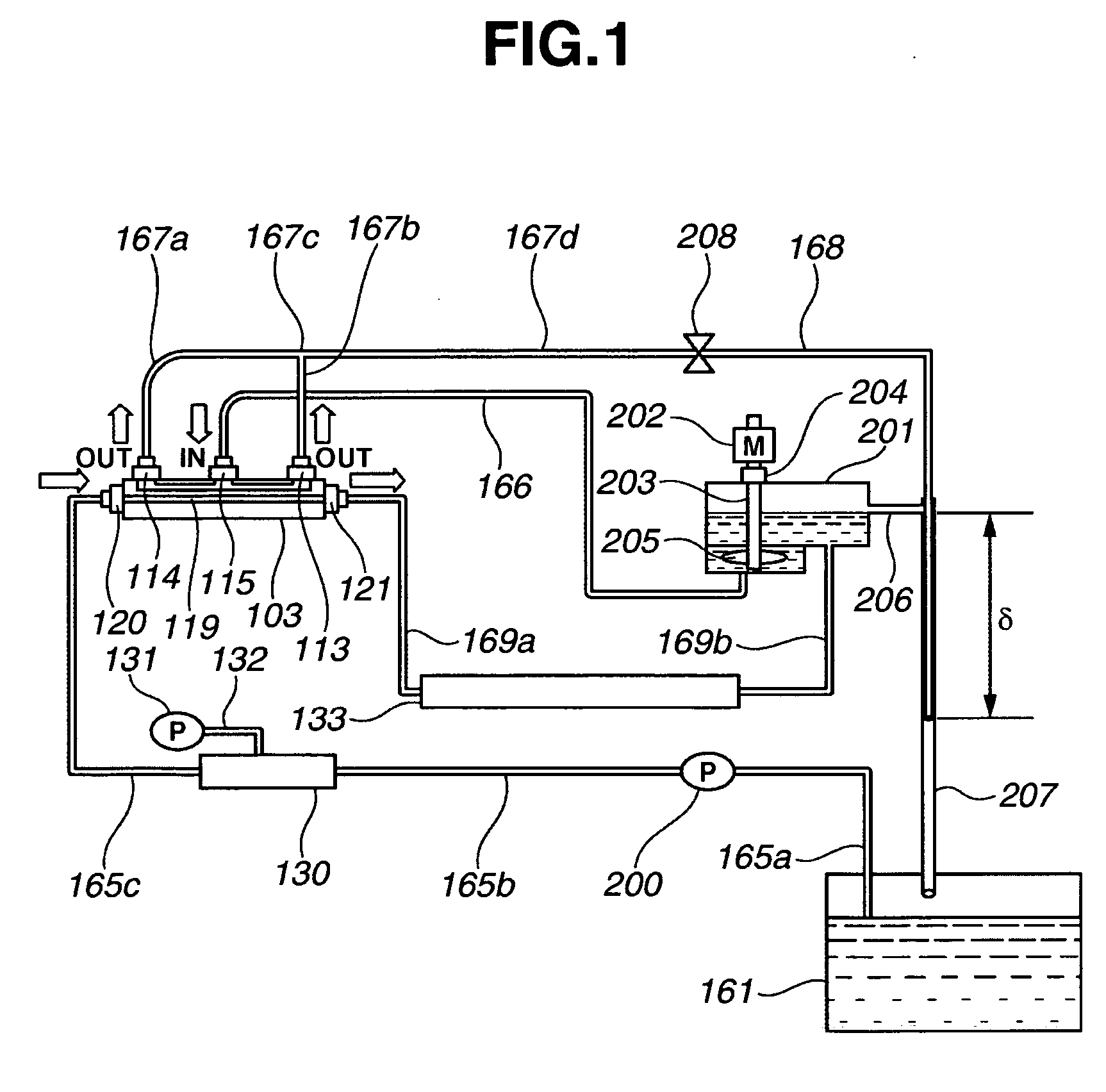
[0229] A liquid jet recording apparatus according to a second embodiment of the present invention is described below with reference to FIG. 10, FIG. 11A, and FIG. 11B.

[0230]FIG. 10 is a view showing the configuration of an ink supply system of the liquid jet recording apparatus according to the second embodiment of the present invention. FIG. 11A and FIG. 11B are views showing the configuration of a gear pump used as a liquid suction pump 163 in the second embodiment. The configuration of the ink supply system is mostly similar to the configuration as described in the first embodiment. However, some portion of the configuration is different from the configuration as described in the first embodiment. Therefore, an explanation as to the portion that is the same as the configuration in the first embodiment is not repeated here, and the explanation is made only as to the portion that is different from the configuration in the first embodiment.

[0231] In the configuration of the ink su...

third embodiment

[0288] A liquid jet recording apparatus according to a third embodiment of the present invention is described below with reference to FIG. 12.

[0289] The third embodiment of the present invention is different from the second embodiment in the points that the de-aerating device 130 is disposed on the downstream side of the sub-tank 201 and that the front end of the tube 168 is connected to the liquid reserve tank 161. Except for these points, the configuration of the third embodiment is similar to the configuration of the second embodiment.

[0290] In the third embodiment, since the de-aerating device 130 is disposed at a position immediately close to the liquid jet head 103, it is possible to allow the capacity of the de-aerating device 130 itself and the capacity of a section including the vacuum pump 131 to be lower than those in the case of the second embodiment.

[0291] Thus, the configuration of the liquid jet recording apparatus according to the third embodiment is more suitable...


PUM


Abstract

A liquid jet recording apparatus includes a liquid jet head including discharge ports, element substrates, a base substrate, common liquid chambers, and a head liquid chamber. The apparatus also includes a first liquid supply path that leads from a liquid reserve tank to a liquid indraft orifice provided on the base substrate via a pump, a second liquid supply path that leads from a liquid outflow orifice provided on the base substrate to a sub-tank, a third liquid supply path that leads from the sub-tank to a liquid indraft orifice provided on the head liquid chamber, a fourth liquid supply path that leads from a liquid outflow orifice provided on the head liquid chamber to the liquid reserve tank or the sub-tank, and a fifth liquid supply path that leads from the sub-tank to the liquid reserve tank to return the liquid from the sub-tank to the liquid reserve tank.

Description

BACKGROUND OF THE INVENTION [0001] 1. Field of the Invention [0002] The present invention relates to a liquid jet recording apparatus. [0003] More specifically, the present invention relates to a liquid jet recording apparatus using a full-line type recording head that has a discharge port array with a length substantially equal to the width of a recording medium and that carries out image recording onto substantially the whole surface of a recording medium by relatively scanning the recording medium with the recording head for only one time. [0004] Even more specifically, the present invention relates to a liquid jet recording apparatus that supplies ink to the head from a second tank that is different from a liquid reserve tank. [0005] 2. Description of the Related Art [0006] Conventionally, in a liquid jet head that discharges an ink droplet by utilizing thermal energy such as heat generated by a heater and the like, some of the thermal energy generated by the heater is discharge...

Claims


Application Information

Patent Timeline
Patent Type & Authority Applications(United States)
IPC IPC(8): B41J2/175
CPCB41J2/1408B41J2/17553B41J2202/12B41J2202/20
Inventor SHIGEMURA, YOSHIHIRO
Owner CANON KK
Why Eureka
Try Eureka