
Double seal with getter in flexible organic displays

a flexible, organic display technology, applied in the direction of organic semiconductor devices, instruments, optics, etc., can solve the problems of gas leakage through the entire seal, easy delaminate and fracture of the arrangement, etc., and achieve the effect of improving the seal

Inactive Publication Date: 2006-06-29
KONINKLIJKE PHILIPS ELECTRONICS NV
View PDF5 Cites 10 Cited by
  • Summary
  • Abstract
  • Description
  • Claims
  • Application Information

AI Technical Summary

Benefits of technology

[0006] It is therefore an object of the present invention to provide flexible displays having improved seals.
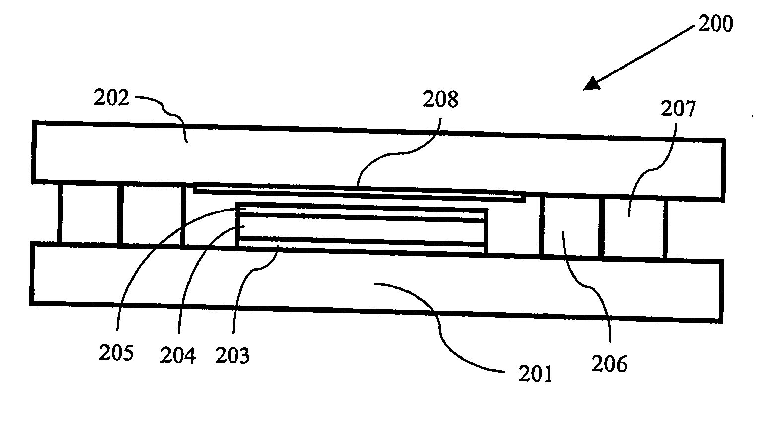
[0009] The inner seal portion is designed to provide for the required impermeability, and is thus made relatively rigid. Using only such a seal, the arrangement would readily delaminate and fracture when bent. However, combining the inner, rigid seal with an outer, flexible seal portion provides for the required robustness. The strength in such an outer seal portion is surprisingly not only enough to secure the substrate joint when bent, but also to substantially reduce the tendency of the rigid inner seal portion to fracture. This is crucial, since any fractures in the inner seal portion would create gas leakages through the entire seal even if the outer seal portion is still unbroken. This is so due to the permeability of the outer seal portion, which in turn is a consequence of the flexibility requirements.
[0010] It has thus been found that the inventive composite seal provides for substantially increased structural strength in the assembly. The flexible outer seal distributes the stresses that occur due to bending of the display. The resulting stress distribution thus lowers the tensile force between the substrates and therefore decreased the risk for substrate delamination.
[0014] The outer seal portion is preferably formed out of a material having a young's modulus lower than 50 MPa, and even more preferably lower than 10 MPa. Materials being this flexible provides for the robustness necessary to avoid substrate delaminations and fractures in the inner seal portion when the display is bent.

Problems solved by technology

Using only such a seal, the arrangement would readily delaminate and fracture when bent.
This is crucial, since any fractures in the inner seal portion would create gas leakages through the entire seal even if the outer seal portion is still unbroken.

Method used


Image

  • Double seal with getter in flexible organic displays
  • Double seal with getter in flexible organic displays
  • Double seal with getter in flexible organic displays

Examples


Embodiment Construction

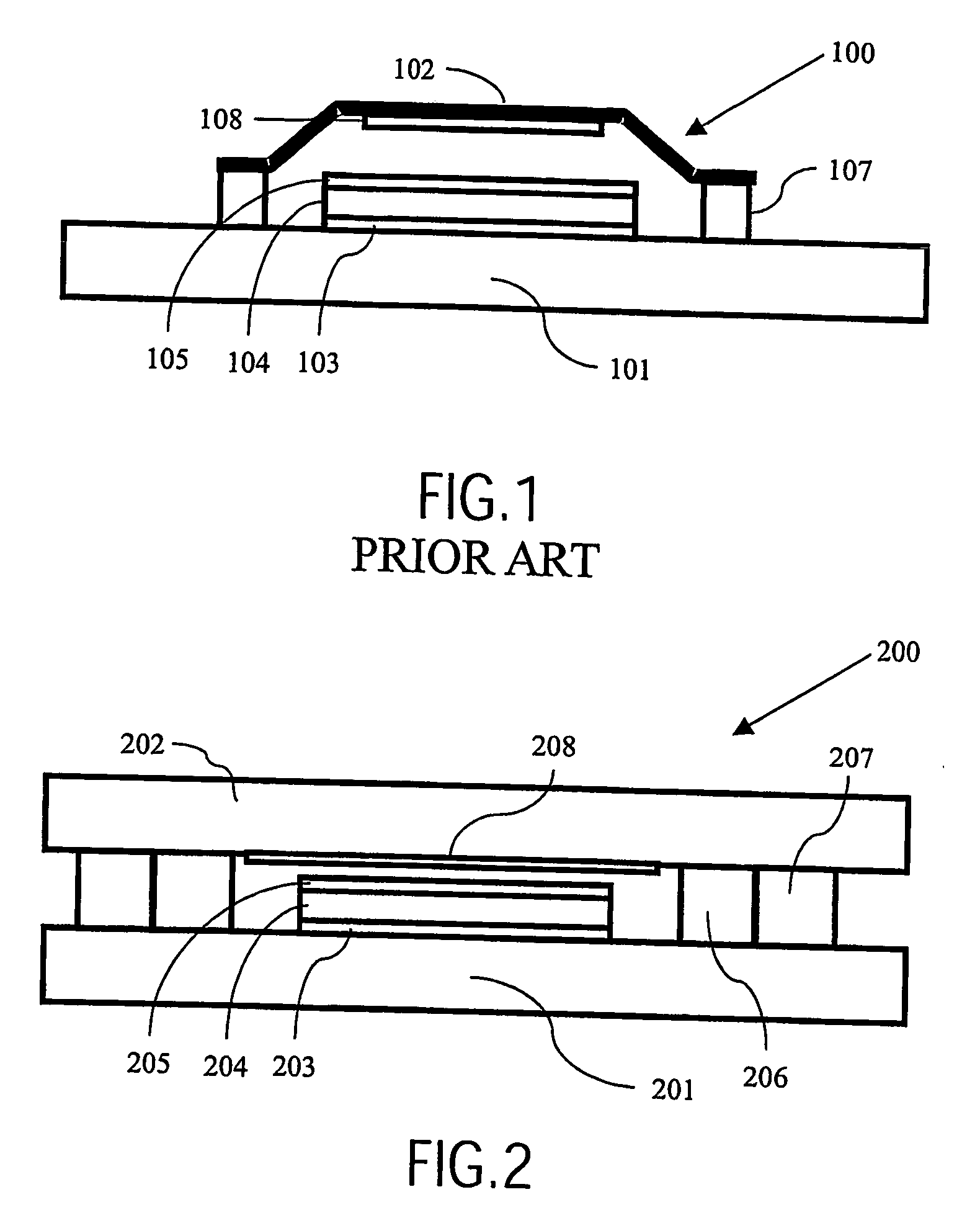
[0023]FIG. 1 shows a cross section of a rigid, prior art display 100. The display comprises a back plane 101 on which an organic light emitting polymer 104 is arranged between an anode 103 and a cathode 105. A metallic back cover 102 is spaced apart from the back plane by means of seals 107 thus forming a closed display cell. Finally, a getter 108 is arranged on the metallic lid 102 inside the display cell. In FIG. 1 as well as in the following figures, the seals have a exaggerated thickness in order to increase readability. The substrates in a typical display device can for example be about 0.1 mm thick and the seals can be about 0.01 mm, the seals thus being substantially thinner than the substrates.

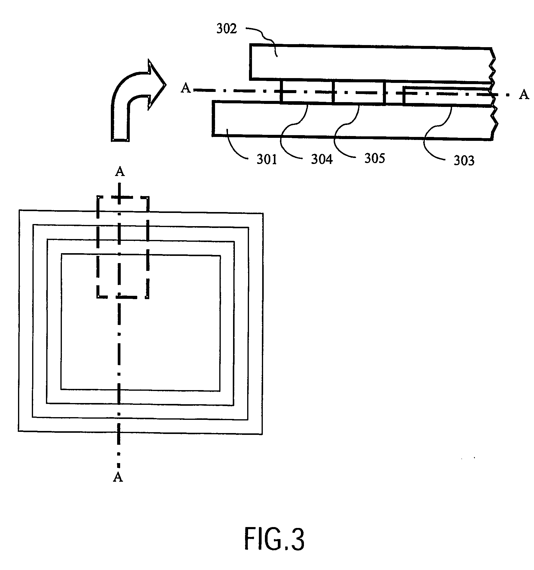
[0024]FIG. 2 shows a cross section of an inventive, flexible display 200 having an inner seal portion 206 and an outer seal portion 207 encapsulating the display cell. Both the back plane 201 and the cover substrate 202 are formed out of a flexible material, for example a polycarbonat...


PUM


Abstract

Improved seal for flexible organic light emitting displays are provided. For the purpose of the present invention it is realisd that a homogenous seal cannot provide for the combination of resuired robusness and required impermeability, which are essential for the life time of the display. Therefore, a seal comprising an inner seal portion and an outer seal portion is proposed. The outer seal portion is flexible as compared to the inner seal portion and the inner seal portion is impermeable as compared to the outer seal portion and being deposited between the outer seal portion and the display element.

Description

FIELD OF THE INVENTION [0001] The present invention relates to flexible organic displays. TECHNOLOGICAL BACKGROUND [0002] Flexible displays are a great challenge towards new markets. Basically, flexible displays can be manufactured using known display elements, e.g. Liquid Crystal Display (LCD) elements or Organic Light Emitting Display (OLED) elements, deposited on flexible substrates, e.g. polymer substrates. For example, Philips has demonstrated a flexible display based on liquid crystal materials. The use of light emitting polymers offers the advantage of excellent viewing angle, contrast and low power consumption. Flexible passive matrix monochrome organic light emitting displays (OLEDs) have been demonstrated by US and Far East companies, such as Pioneer, Dai Nippon, UDC, and DuPont Displays. [0003] Generally, an OLED comprises an organic display element which is deposited on a base glass substrate and covered by an exit substrate. One of the critical issues for Organic Light ...

Claims


Application Information

Patent Timeline
IPC IPC(8): G02F1/1339H01L51/10H01L51/52
CPCH01L2251/5338H01L51/5246H01L2251/55H10K2102/311H10K59/8722H10K59/874H05B33/04H10K50/8426H10K2101/00
Inventor JANSSEN, ESTHER ANNA WILHELMINA GERARDADIRKZWAGER, MAARTENZUIDEMA, HANSVAN VEENEN, EDUARDNISATO, GIOVANNIMUTSAERS, CORNELIS ADRIANUS HENRICUS ANTONIUSBUIJK, OSCAR JOHANNES ANTOINETTABOUTEN, PETRUS CORNELIS PAULUS
Owner KONINKLIJKE PHILIPS ELECTRONICS NV
Learn More