Optical inclination sensor

a technology of inclination sensor and optical inclination sensor, which is applied in the direction of optical radiation measurement, instruments, and mechanical means, etc., can solve the problem of limited light from the sour

Inactive Publication Date: 2006-06-29
BAKER HUGHES INC
View PDF19 Cites 26 Cited by
  • Summary
  • Abstract
  • Description
  • Claims
  • Application Information

AI Technical Summary

Problems solved by technology

Therefore, the light from the source is limited in reaching the sensor depending upon the position of the ball.

Method used


Image

  • Optical inclination sensor
  • Optical inclination sensor
  • Optical inclination sensor

Examples


Embodiment Construction

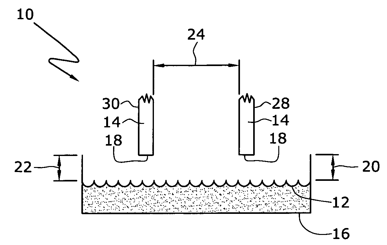
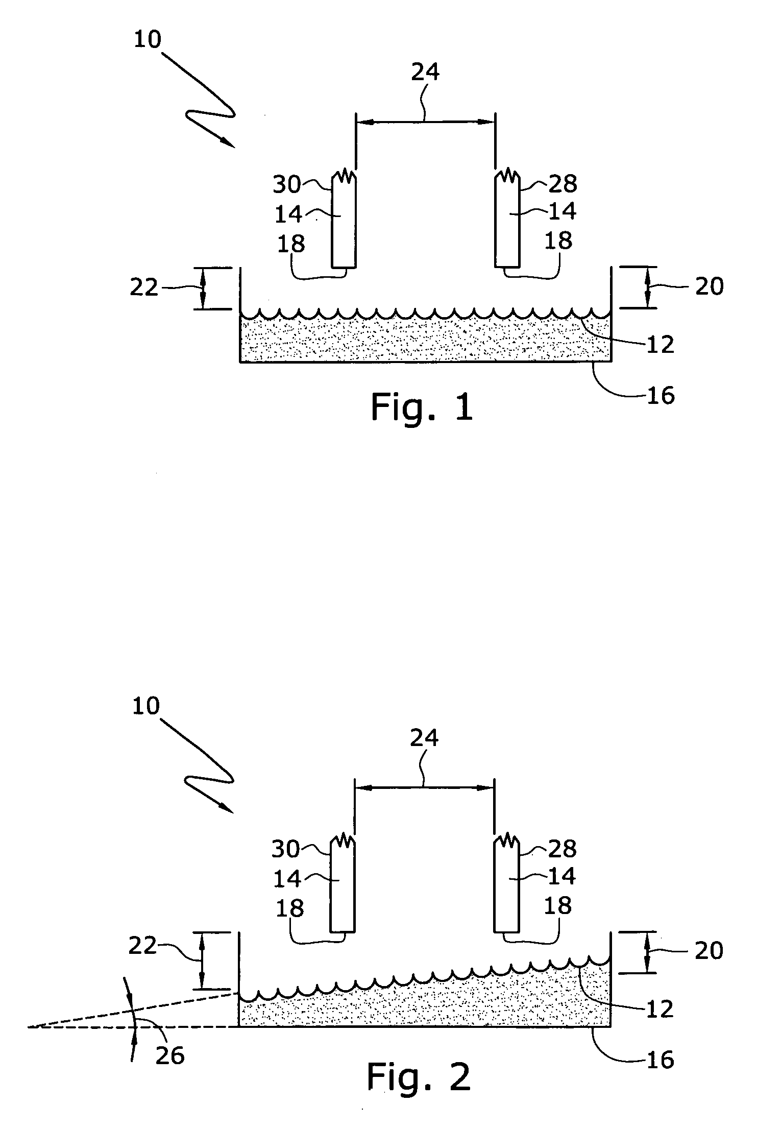
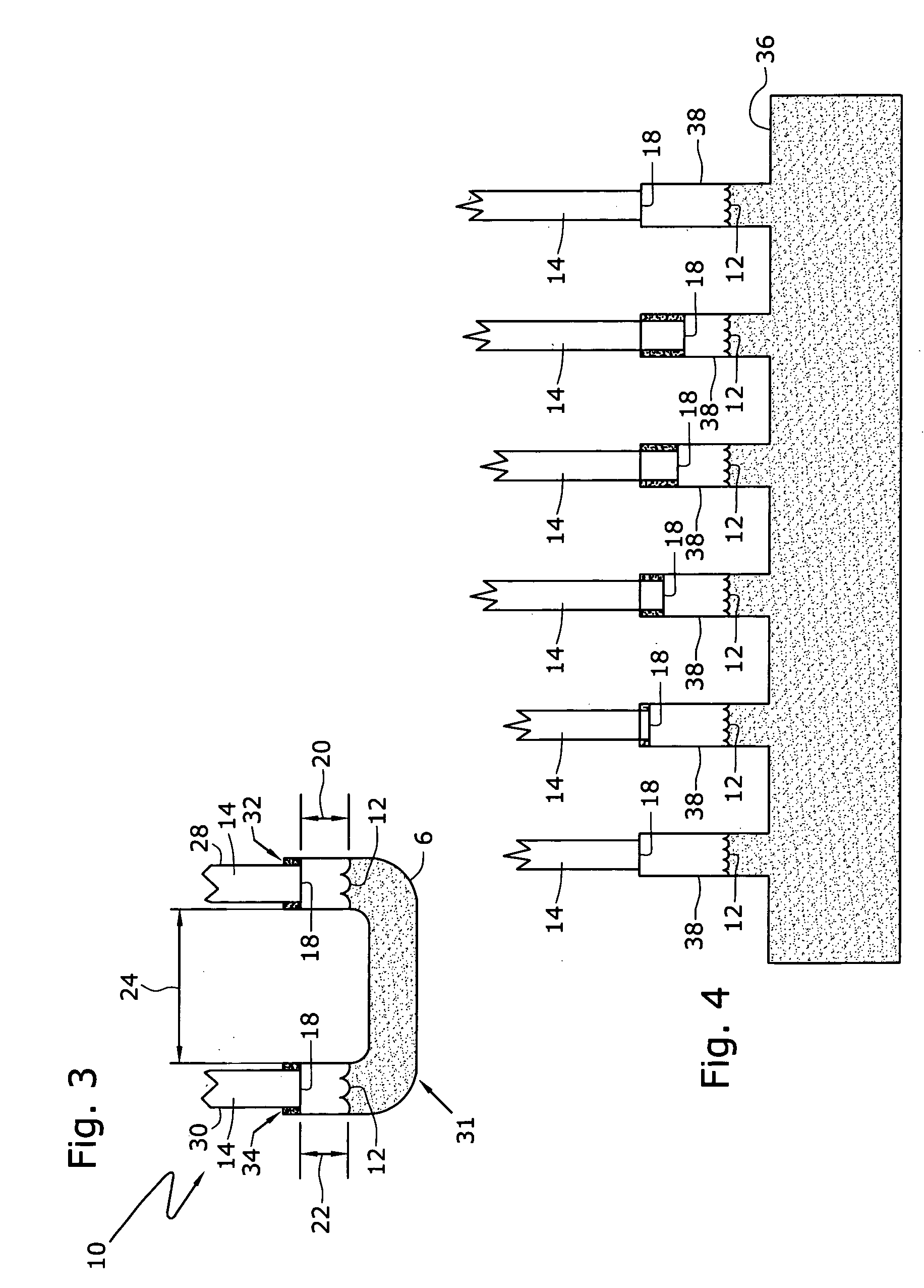
[0023] A fiber optic inclination sensor or tilt meter in accordance with one aspect of the present invention includes two or more optical fibers, each having a cleaved fiber end face that is placed in proximity to a reflective tiltable surface. As used herein, a tiltable surface is a surface that maintains a consistent horizontal level even when, for example, a container or housing in which the surface and the fibers are disposed, is tilted. Suitable tiltable surfaces include spring loaded or biased surfaces and liquid surfaces, for example the surface of mercury, water-based liquids, or oils. If mercury is used, care should be taken so that the surface tension between mercury and the walls of the container do not affect the flatness of the tiltable surface. Each optical fiber end face is spaced from the reflective surface by a predetermined gap length.

[0024] Referring initially to FIG. 1, optical tilt or inclination sensor 10 in accordance with an embodiment of the present inventi...


PUM


Abstract

An optical inclination sensor is provided having at least one reflective surface and at least two separate optical fibers having ends spaced from a reflective surface. As the reflective surface tilts with respect to a pre-determined reference position the gap lengths between the fiber ends and the reflective surface change and the differences in these gap lengths is used to calculate an angle of inclination with respect to a reference position. The optical inclination sensor can include at least one mass attached to a housing and moveable with respect to the housing as the mass and housing are rotated about one or more axes. Optical strain sensors are disposed a various locations between the mass and housing so that as the mass moves with respect to the housing, each one of the optical strain sensors are placed in compression or tension. The housing can be a generally u-shaped housing having two arms and a base section with the mass disposed within the housing. Alternatively, the housing includes a first beam, and the mass is a second beam arranged generally orthogonal to the first beam and pivotally attached thereto. The optical strain sensors are disposed between the first beam and the second beam. The optical strain sensors are placed in tension or compression as the second beam pivots with respect to the first beam.

Description

FIELD OF THE INVENTION [0001] This invention generally relates to sensors for measuring angles of inclination. More particularly, the present invention relates to inclination sensors utilizing optical interferometers. BACKGROUND OF THE INVENTION [0002] Tilt meters or tilt sensors are used in the geophysical sciences and other applications to measure tilt or inclination of the ground or of structures. These measurements can be taken at the surface or, particularly in the case of geophysical applications, below the surface of the Earth in, for example, gas or oil wells. In these applications, the tilt meters are used to provide information about the general shape of a well or of sudden turns in the well. For example, oil wells can extend 10,000 or 30,000 feet below the surface of the Earth. At these depths, the wells can develop helical or corkscrew bores. These bores need to be monitored and tracked during the drilling process. In addition, highly sensitive tilt sensors are used in o...

Claims


Application Information

Patent Timeline
Patent Type & Authority Applications(United States)
IPC IPC(8): G01B11/26G01J1/56
CPCG01C9/06G01C9/20G01C2009/066G01D5/268
Inventor CHILDERS, BROOKS A.BOYD, CLARK DAVISRITCHIE, NORMAN WAYNEZERWEKH, PAUL SAMUELHESTER, STEPHEN E.
Owner BAKER HUGHES INC
Why Eureka
Try Eureka