
Compact spectrometer

a compact, spectrometer technology, applied in the direction of spectral investigation, instruments, electric discharge lamps, etc., can solve the problems of reducing the readout time and evaluation time, reducing the expenditure on adjustment, and reducing the adjustment expenditure. , the effect of reducing the amount of adjustment and assembly

Active Publication Date: 2006-06-29
CARL ZEISS MICROSCOPY GMBH
View PDF16 Cites 44 Cited by
  • Summary
  • Abstract
  • Description
  • Claims
  • Application Information

AI Technical Summary

Benefits of technology

[0012] It is the primary object of the present invention to develop a spectrometric arrangement which has compact dimensions and in which the expenditure required for adjustment and assembly is minimized.
[0014] Due to its compact structural size and the minimized expenditure on adjustment and assembly required for its manufacture, the spectrometer according to the invention has applications ranging from routine laboratory analysis to special tasks in process measurement technology and quality control in manufacturing processes.

Problems solved by technology

However, the expenditure on adjustment of the optical components, particularly reflection gratings and mirrors, appears to be considerable.
In this solution, expenditure on adjustment is also considerable due to the large number of individual parts.
While this reduces the readout time and evaluating time, the expenditure on adjustment and assembly is increased due to the individual detectors.
However, the spectrometer arrangements mentioned above have the disadvantage that, even with optimized manufacture requiring only a fine adjustment of the optical components, the expenditure on assembly and adjustment is too high due to the quantity of elements to be adjusted.
Accordingly, economical and effective large-scale production is impossible.

Method used


Image

  • Compact spectrometer
  • Compact spectrometer
  • Compact spectrometer

Examples


Embodiment Construction

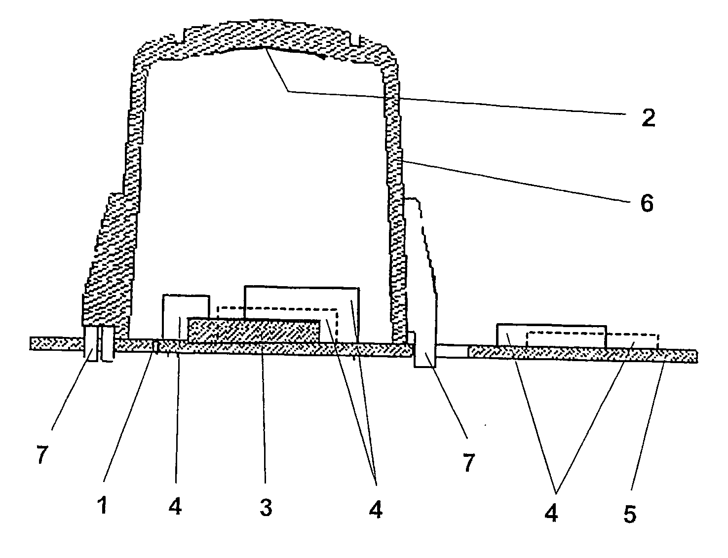
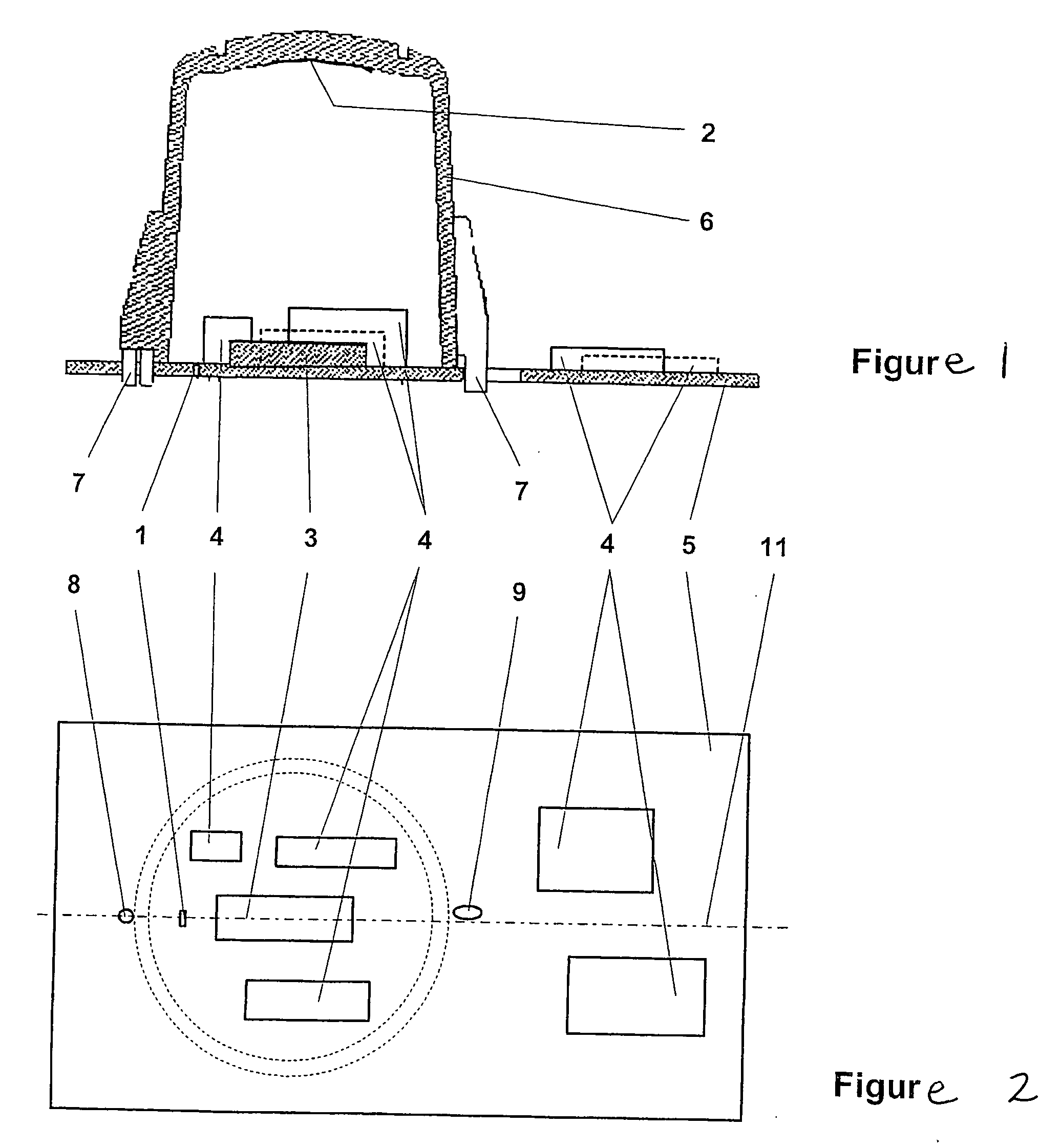
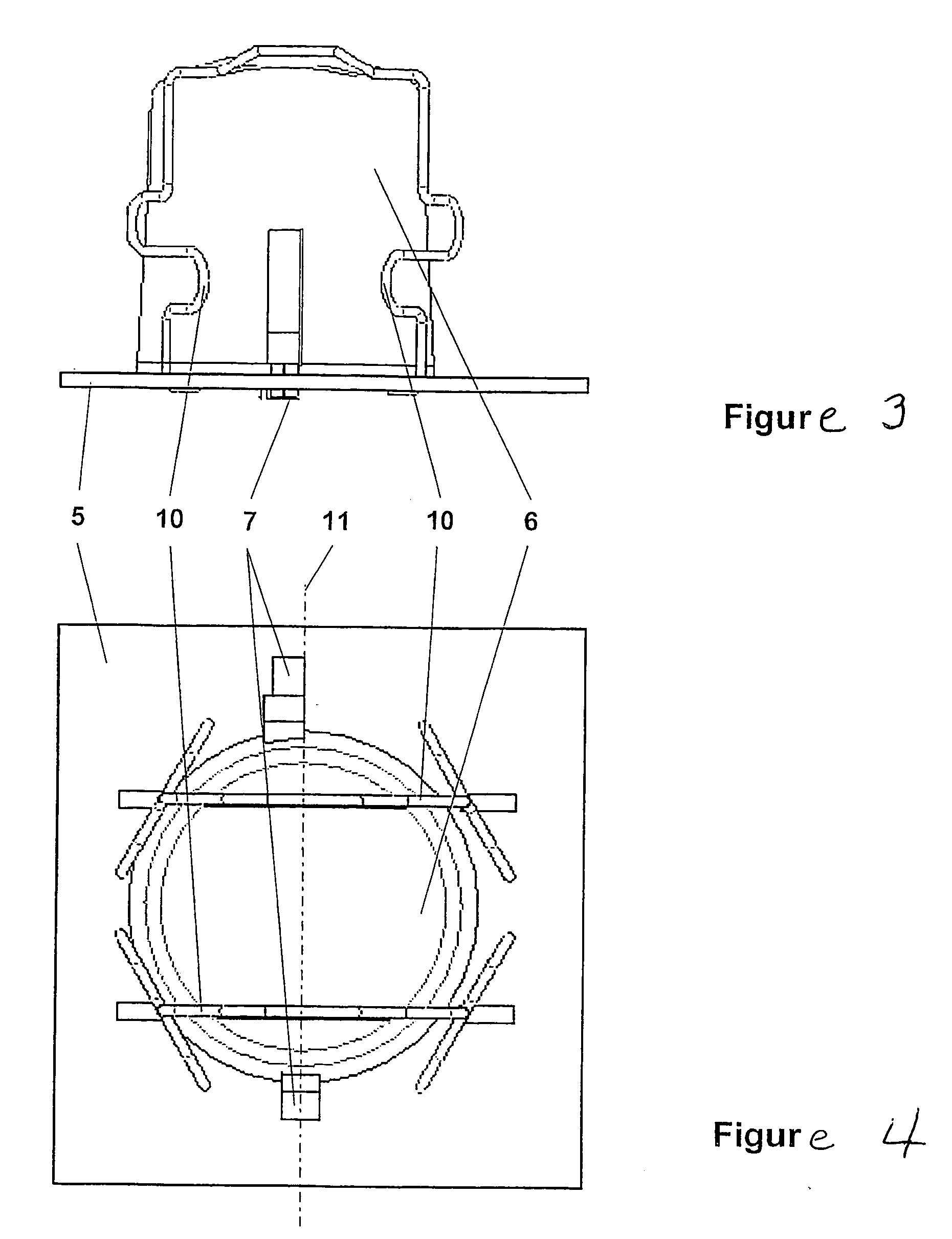
[0021] The compact spectrometer shown in section in FIG. 1 comprises an entrance slit 1, an imaging grating 2, one or more detector elements 3 in rows or matrices, and elements of a controlling and evaluating unit 4. The detector elements 3 and the entrance slit 1 are arranged on a shared support 5, preferably a printed circuit board made of ceramic material, wherein the entrance slit 1 is constructed as a rectangular opening. Additional elements of the controlling and evaluating unit 4 can be arranged on the free surfaces of the support 5 both inside and outside the spectrometer housing 6. The detector elements 3, the entrance slit 1 and the additional elements of the controlling and evaluating unit 4 can be manufactured in the printed circuit board fabricating process with a relatively low expenditure on exact mutual positioning.

[0022] The imaging grating 2 having a spherical shape is arranged in the spectrometer housing 6. The two elements comprise materials with identically hig...


PUM


Abstract

The present invention is directed to a spectrometer in which the electrical and optical components are connected to one another in a compact construction. A minimal expenditure on assembly and adjustment is achieved through a small quantity of individual parts. The compact spectrometer comprises an entrance slit, an imaging grating, one or more detector elements in rows or matrices, and elements of a controlling and evaluating unit. The detector elements and the entrance slit are arranged on a shared support, the elements of the controlling and evaluating unit being arranged on the free surfaces of the support. The entrance slit and the detector elements and the imaging spherical grating recessed into the spectrometer housing are arranged symmetric to an imaginary center axis of the support. Due to its compact size and the minimized expenditure on adjustment and assembly for its manufacture, the spectrometer according to the invention has applications ranging from routine laboratory analysis to special tasks in process measurement technique and quality control in manufacturing processes.

Description

CROSS-REFERENCE TO RELATED APPLICATIONS [0001] This application claims priority of International Application No. PCT / EP2003 / 014588, filed Dec. 19, 2003, and German Application No. 103 04 312.8, filed Feb. 4, 2003, the complete disclosures of which are hereby incorporated by reference.BACKGROUND OF THE INVENTION [0002] a) Field of the Invention [0003] The present invention is directed to a compact spectrometer in which the electrical and optical components are permanently connected to one another. A minimal expenditure on assembly and adjustment is achieved through a small quantity of individual parts. [0004] b) Description of the Related Art [0005] According to the known prior art, miniaturized spectrometer systems are often needed so as to ensure a broad range of application. The combination of high-performance digital electronics with the optical components and the use of flexible light-conducting fibers results in spectrometers whose areas of application range from routine analys...

Claims


Application Information

Patent Timeline
Patent Type & Authority Applications(United States)
IPC IPC(8): G01J3/28G01J3/02
CPCG01J3/02G01J3/0256G01J3/0291
Inventor KERSTAN, FELIXKLARNER, ULLRICHCORRENS, NICOTUMPACH, GREGOR
Owner CARL ZEISS MICROSCOPY GMBH
Learn More