
Liquid crystal display and backlight module thereof

Inactive Publication Date: 2006-06-29
PRODISC TECH INC
View PDF1 Cites 230 Cited by
  • Summary
  • Abstract
  • Description
  • Claims
  • Application Information

AI Technical Summary

Benefits of technology

[0011] In view of the foregoing, the invention is to provide a liquid crystal display and a backlight module thereof, which can equalize the light emitted from the light sources and can control the angle and direction of the emitted light.
[0014] As mentioned above, the liquid crystal display and backlight module of the invention can equalize the light emitted from the light sources and can control the angle and direction of the emitted light. Comparing with the prior art, the invention utilizes a plurality of Fresnel areas to adjust the angle and direction of the emitted light, which can achieve the demands of brightness and viewing angle under different conditions. Accordingly, the liquid crystal display of the invention can achieve the demands of wide viewing angle and high brightness. In addition, since the invention can control the angle and direction of the emitted light, the dark zones at the intervals between every two neighbor conventional LEDs can be prevented. Thus, the light uniformity of the liquid crystal display of the invention can be improved.

Problems solved by technology

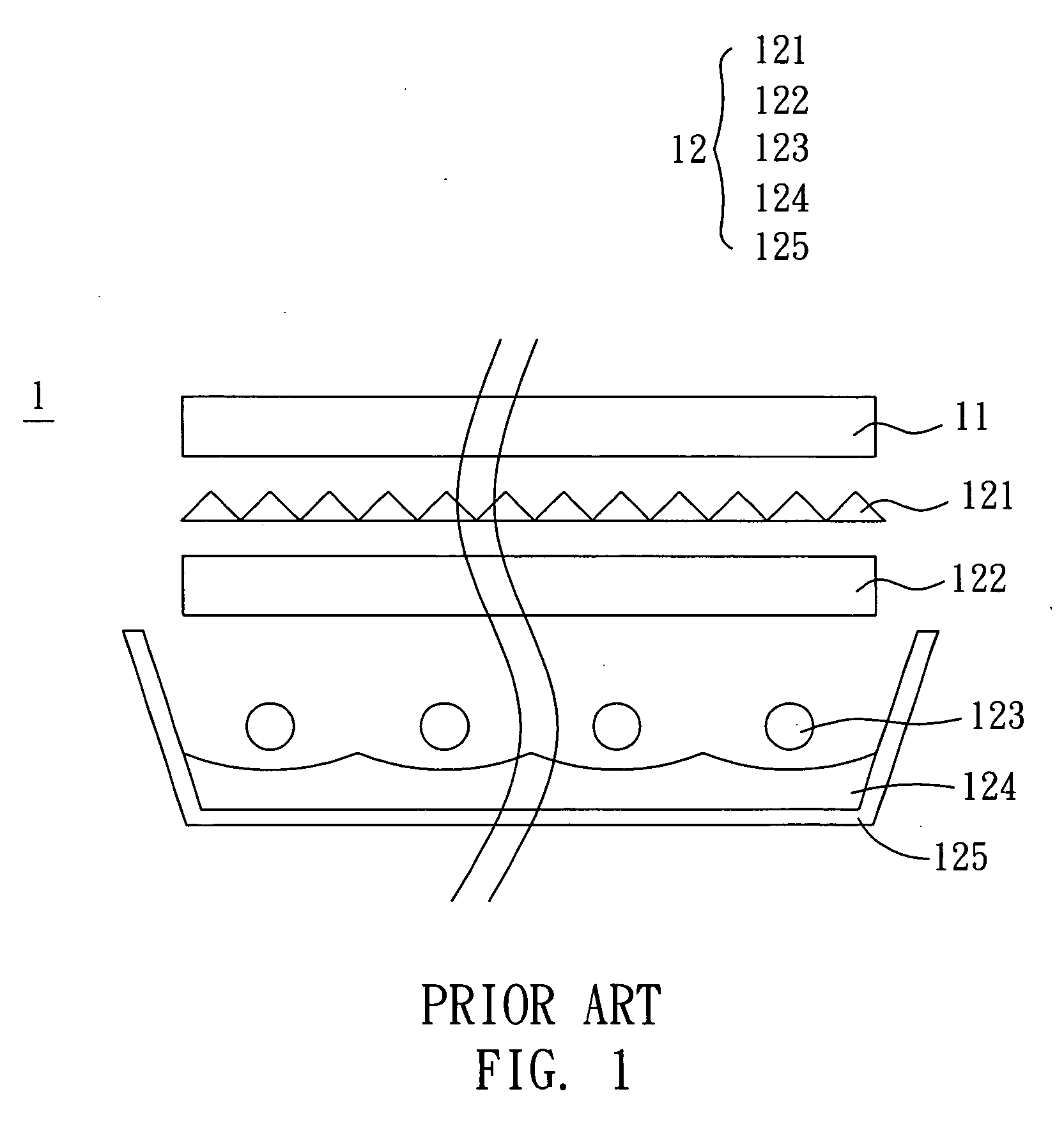
Therefore, the intervals between every two neighbor LEDs may show dark zones, which affect the uniformity of the entire device.
Otherwise, in order to satisfy the demand of central brightness, the consideration of viewing angle must be sacrificed so that the demand of wide viewing angle may not be achieved.

Method used


Image

  • Liquid crystal display and backlight module thereof
  • Liquid crystal display and backlight module thereof
  • Liquid crystal display and backlight module thereof

Examples


Embodiment Construction

[0023] The present invention will be apparent from the following detailed description, which proceeds with reference to the accompanying drawings, wherein the same references relate to the same elements.

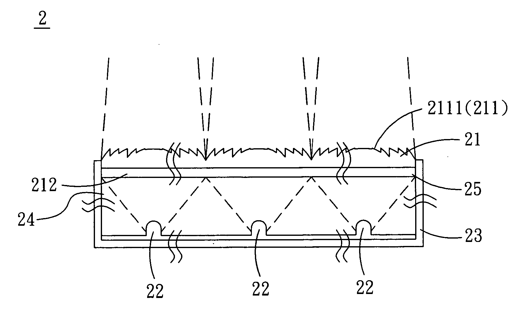
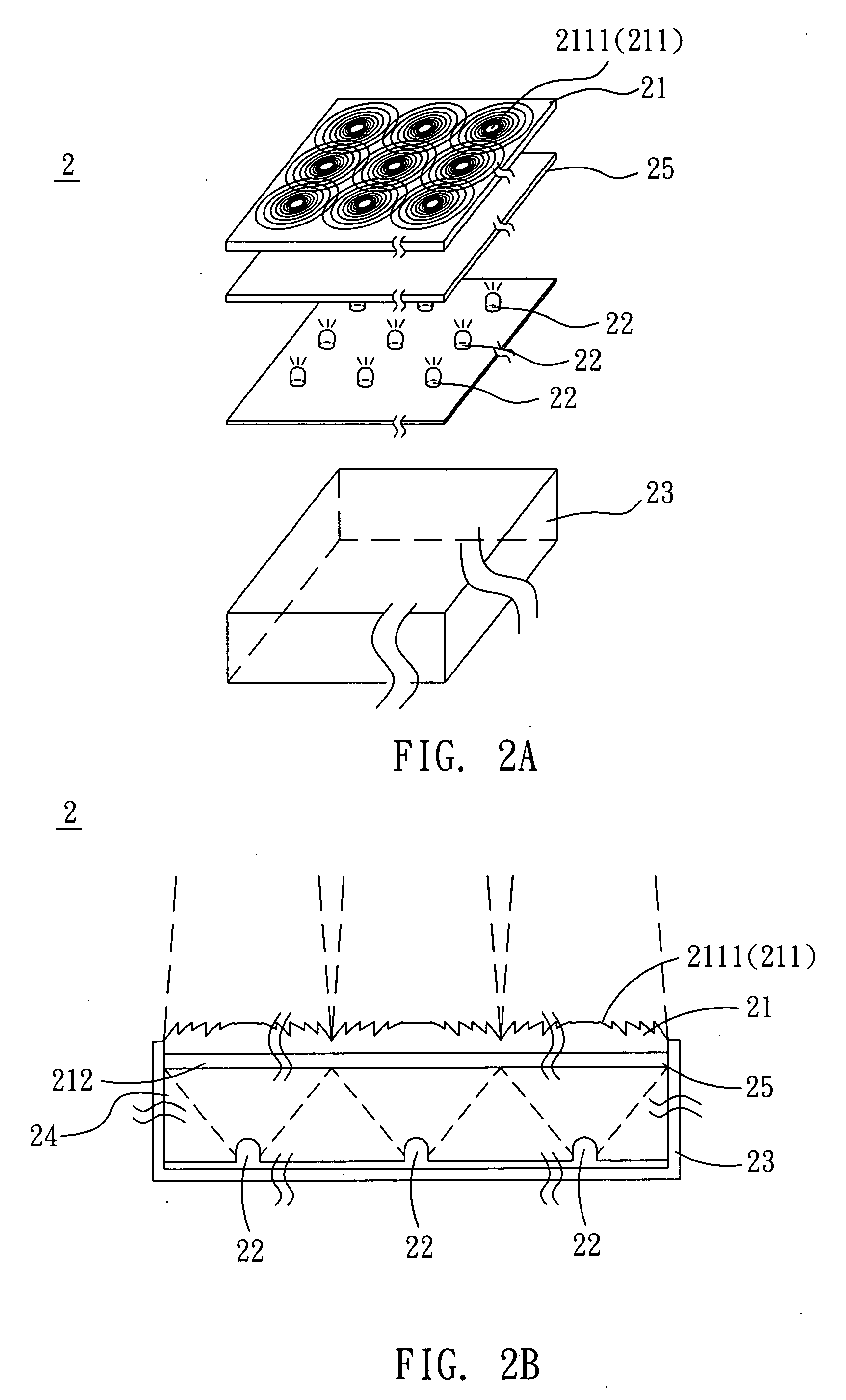
[0024] With reference to FIGS. 2A and 2B, a backlight module 2 according to a preferred embodiment of the invention includes an optical film substrate 21 and a plurality of light sources 22. In the embodiment, the optical film substrate 21 has a first surface 211 and a second surface 212 opposite to the first surface 211. The first surface 211 has a plurality of Fresnel areas 2111. In the present embodiment, the Fresnel areas 2111 are located on the first surface 211 in an array arrangement.

[0025] A plurality of light sources 22 are disposed at one side of the optical film substrate 21. In this embodiment, the light sources 22 are light-emitting diodes (LEDs) and the light sources 22 are located facing to the first surface 211 in an array arrangement so as to provide an LED array. ...


PUM


Abstract

A backlight module includes an optical film substrate and a plurality of light sources. The optical film substrate has a first surface and a second surface opposite to the first surface. The first surface of the optical film substrate has a plurality of Fresnel areas. The Fresnel areas are disposed on the first surface in an array arrangement. The light sources are disposed at one side of the optical film substrate. In addition, a liquid crystal display including the backlight module is provided.

Description

BACKGROUND OF THE INVENTION [0001] 1. Field of Invention [0002] The invention relates to a display and a backlight module, and, in particular, to a liquid crystal display and a backlight module thereof. [0003] 2. Related Art [0004] In the coming multimedia age, the usable displays have been developed and have various types. In the present displays, flat panel displays have the advantages of light weight and thinner thickness, so that they are one of the mainstreams in this industry. [0005] Regarding to the flat panel displays, the liquid crystal display has the advantages of full color, high resolution, thinner thickness, power saving and high contrast, so it has broader application fields. For example, the application fields of the liquid crystal display include small area applications such as the mobile phone screen and the display panel in car, middle size applications such as the monitor of a laptop computer or a desktop computer, and the latest large size applications such as t...

Claims


Application Information

Patent Timeline
IPC IPC(8): F21V7/04
CPCG02B3/0056G02B3/08G02F1/133526G02F1/133603G02F1/133606G02F1/133611G02F2001/133607G02F1/133607
Inventor CHOU, YEN-CHUNCHIU, CHUNG-MO
Owner PRODISC TECH INC
Learn More