
Optical transceiver with optical sub-module thermally couples with optical transceiver without mechanical stress

Active Publication Date: 2006-06-29
SUMITOMO ELECTRIC IND LTD
View PDF4 Cites 38 Cited by
  • Summary
  • Abstract
  • Description
  • Claims
  • Application Information

AI Technical Summary

Benefits of technology

[0009] Since the box portion is adhered to the support member with a thermal grease therebetween and free in positional with respect to directions parallel to the primary surface of the housing, and the supporting member is adhered to the housing with adjustable in a position vertical to the primary surface of the housing. Therefore, the present optical transceiver can make it consistent to optically couple the transmitting module with the housing in accurate and to thermally couple the transmitting module with the housing.

Problems solved by technology

Especially, the power consumption of devices far increases compared with the case that the transmission speed is 1 GHz or less.
When the assembly of the optical transceiver is carried out by taking the thermal coupling primarily into consideration, the accurate optical coupling may be not always obtained.
Rather, the coupling characteristic inferior to the optimal one is often encountered.
Contrary, when the optical coupling is the first priority, the heat dissipation is rarely achieved with acceptable efficiency.

Method used


Image

  • Optical transceiver with optical sub-module thermally couples with optical transceiver without mechanical stress
  • Optical transceiver with optical sub-module thermally couples with optical transceiver without mechanical stress
  • Optical transceiver with optical sub-module thermally couples with optical transceiver without mechanical stress

Examples


Embodiment Construction

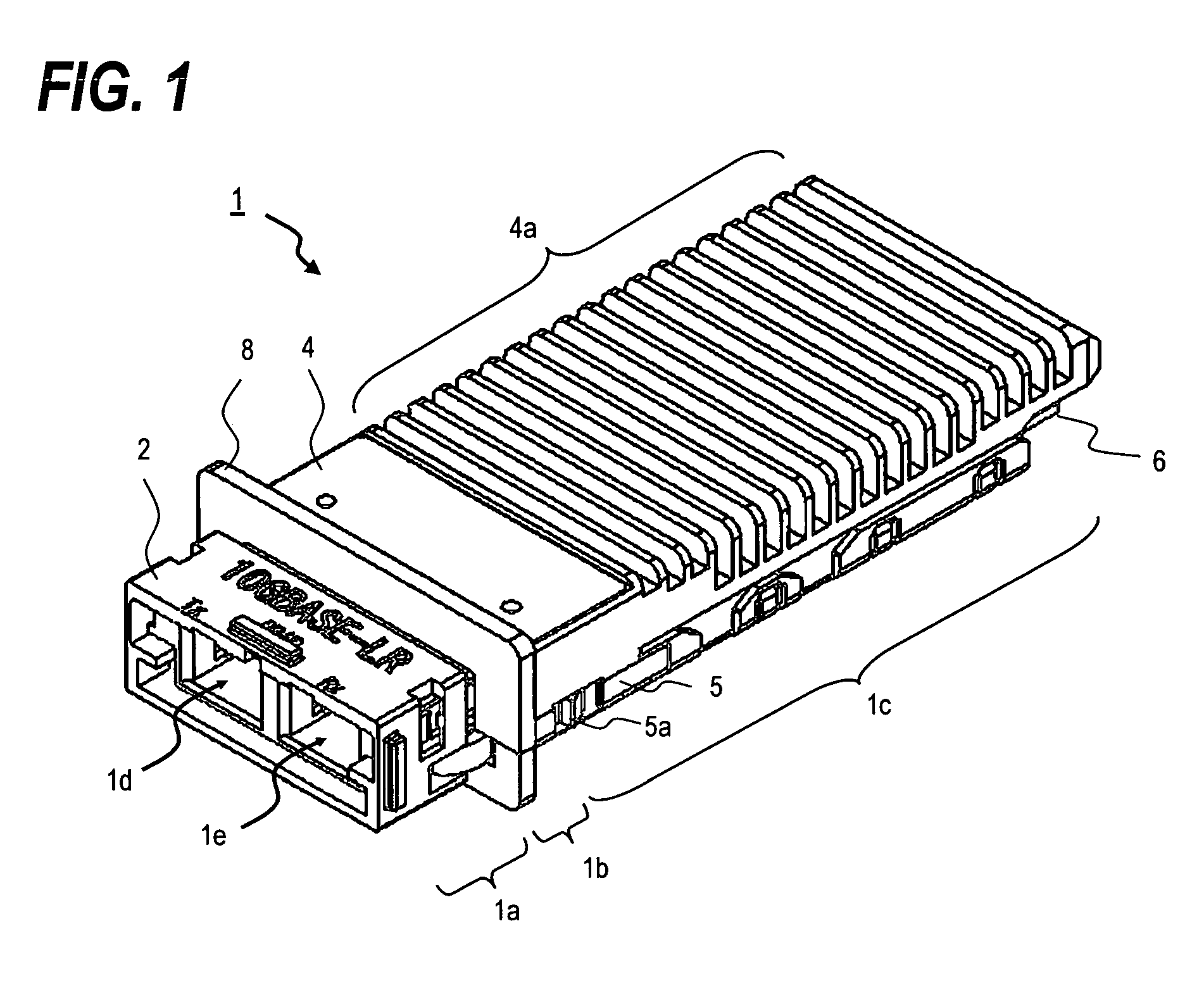
[0018]FIG. 1 is a perspective view of the optical transceiver 1 according to the present invention. The transceiver 1 roughly comprises a receptacle portion 1a, a flange portion 1b, and a circuit portion 1c. The receptacle portion 1a provides two openings, 1d and 1e, corresponding to a transmitting receptacle 1d and a receiving receptacle 1e, respectively. The transceiver 1 also provides a grip 2 surrounding these openings. By sliding the grip 2 frontward and rearward, the transceiver can be released from the host system on which the transceiver 1 is installed.

[0019] The flange portion 1b has a flange 8. When the transceiver 1 is installed on the host system, the front side of this flange 8 extrudes from the face panel of the host system to expose the openings, 1d and 1e, to make it possible that the optical connector can be engaged with the openings from the front of the host system. Behind the flange 8 is formed with the circuit portion 1c. The circuit portion 1c installs the sub...


PUM


Abstract

An optical module free from the mechanical stress and used in an optical transceiver is disclosed, even the position of the module is fixed with repect to the hosuing not only from the viewpoint of the optical alignment but also the heat conduction. The optical module comprises the sleeve portion and the box portion. The sleeve portion is directly fixed to the housing, but the box portion is indirectly fixed to the housing via the support member. Between the box portion and the support member is filled with the thermal grease in one end thereof, while the other end is pressed by the elastice member that presses the box portion against the support member. The box portion is free from the mechanical stress when the sleeve portion is rigidly fixed to the hosuing.

Description

CROSS REFERENCE TO RELATED APPLICATION [0001] This application claims a benefit of a previous application, Ser. No. of 60 / 631,885, filed on Dec. 1, 2004.BACKGROUND OF THE INVENTION [0002] 1. Field of the Invention [0003] The present invention relates to a structure of an optical transceiver, in which an optical sub-module is fixed to the transceiver without mechanical stress. [0004] 2. Related Prior Art [0005] The United States Patent, U.S. Pat. No. 5,943,461, has disclosed an optical transceiver installing optical modules with the pig-tailed type structure for the optical transmission and the optical reception. Optical connectors provided in the end of the pig-tail fiber pulled out from each optical module are set to the housing. A multi-source agreement for such multifunctional optical transceiver has been ruled in the field and published as the X2 standard (X2-MSA). This standard rules the transmission speed of 10 GHz, the pin-assign for the electronic specification, while for th...

Claims


Application Information

Patent Timeline
IPC IPC(8): G02B6/36
CPCG02B6/4201G02B6/4271G02B6/4283G02B6/4256G02B6/4281G02B6/4279
Inventor OKI, KAZUSHIGE
Owner SUMITOMO ELECTRIC IND LTD
Learn More