Coaxial connector integrated connector for board connection

a technology of integrated connectors and coaxial connectors, which is applied in the direction of antenna connectors, two-pole connections, coupling device connections, etc., can solve the problems of not being economical, using a multi-connector in which the characteristic impedance adjustment is described above, etc., and achieves the elimination of cables, high accuracy, and reduced assembly man-hours

Inactive Publication Date: 2006-06-29
HOSIDEN CORP
View PDF5 Cites 28 Cited by
  • Summary
  • Abstract
  • Description
  • Claims
  • Application Information

AI Technical Summary

Benefits of technology

[0011] This invention is one which takes points like these into consideration and has for its object to provide a coaxial connector integrated connector for board connection having few components, not increasing assembly man-hours, and enabling cost reductions.
[0014] According to this invention, as described above, it is possible, by forming a coaxial connector integrally from respectively a receptacle-side insulating housing constituting a multi-connector and a plug-side body, to manufacture in a positional relationship between a multi-connector and a coaxial connector with high accuracy. As a result, it becomes possible to connect, by one pair of connectors, signals requiring impedance matching and signals which, while not requiring impedance matching, are numerous, and there can be implemented a coaxial connector integrated connector for board connection which eliminates cables, reduces assembly man-hours, and makes cost reductions possible.

Problems solved by technology

Consequently, with respect to all signals, there are many cases where using a multi-connector in which the characteristic impedances are adjusted, such as that described above, is not economical.

Method used


Image

  • Coaxial connector integrated connector for board connection
  • Coaxial connector integrated connector for board connection
  • Coaxial connector integrated connector for board connection

Examples


first embodiment

1. First Embodiment

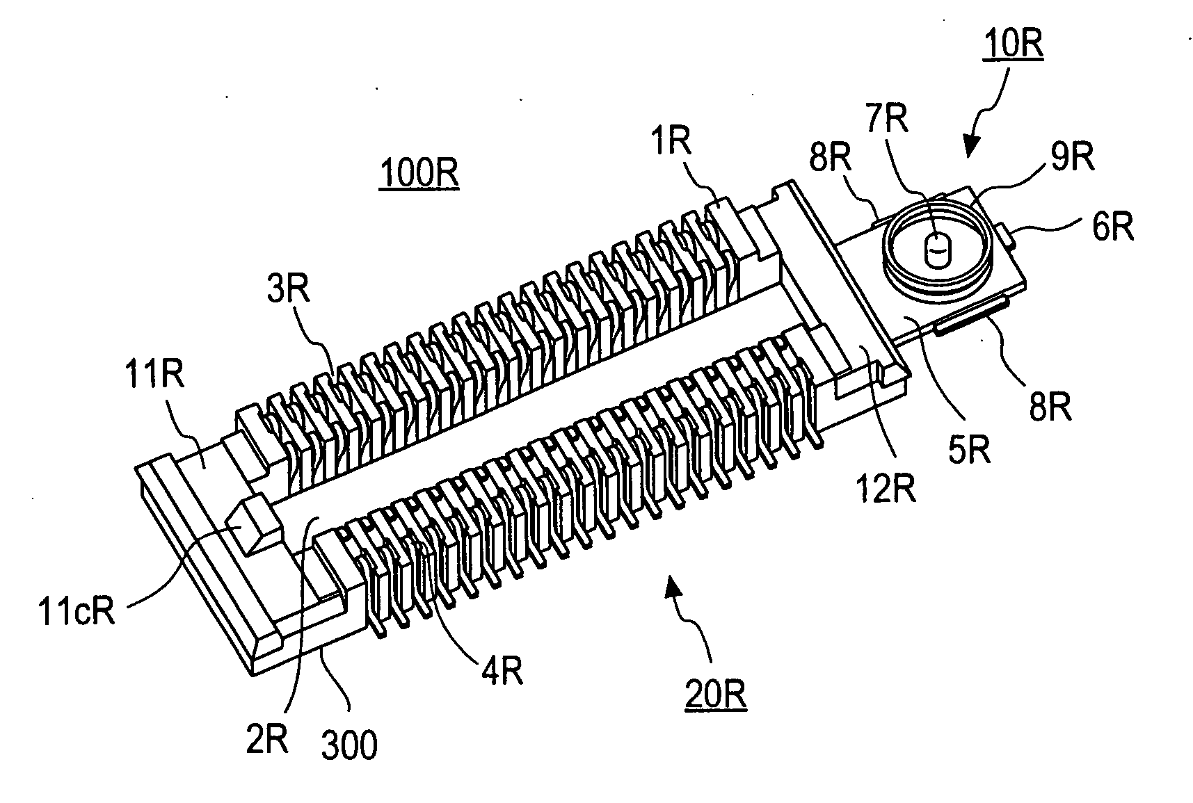
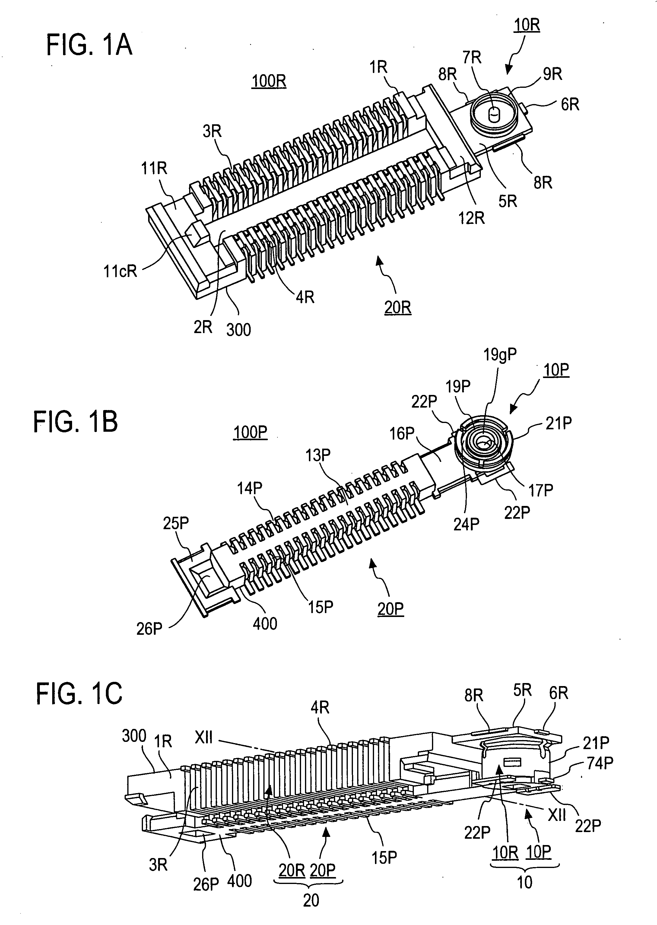
[0037] In FIGS. 1A, 1B, and 1C, there are shown oblique views of a receptacle 100R, a plug 100P, and a state where the two are mated, showing an embodiment of a connector for integrated board connection of a coaxial connector according to this invention. This receptacle 100R and this plug100P are respectively installed on separate boards, and by respectively making them mate, the boards are connected together electrically.

(Configuration of the Receptacle)

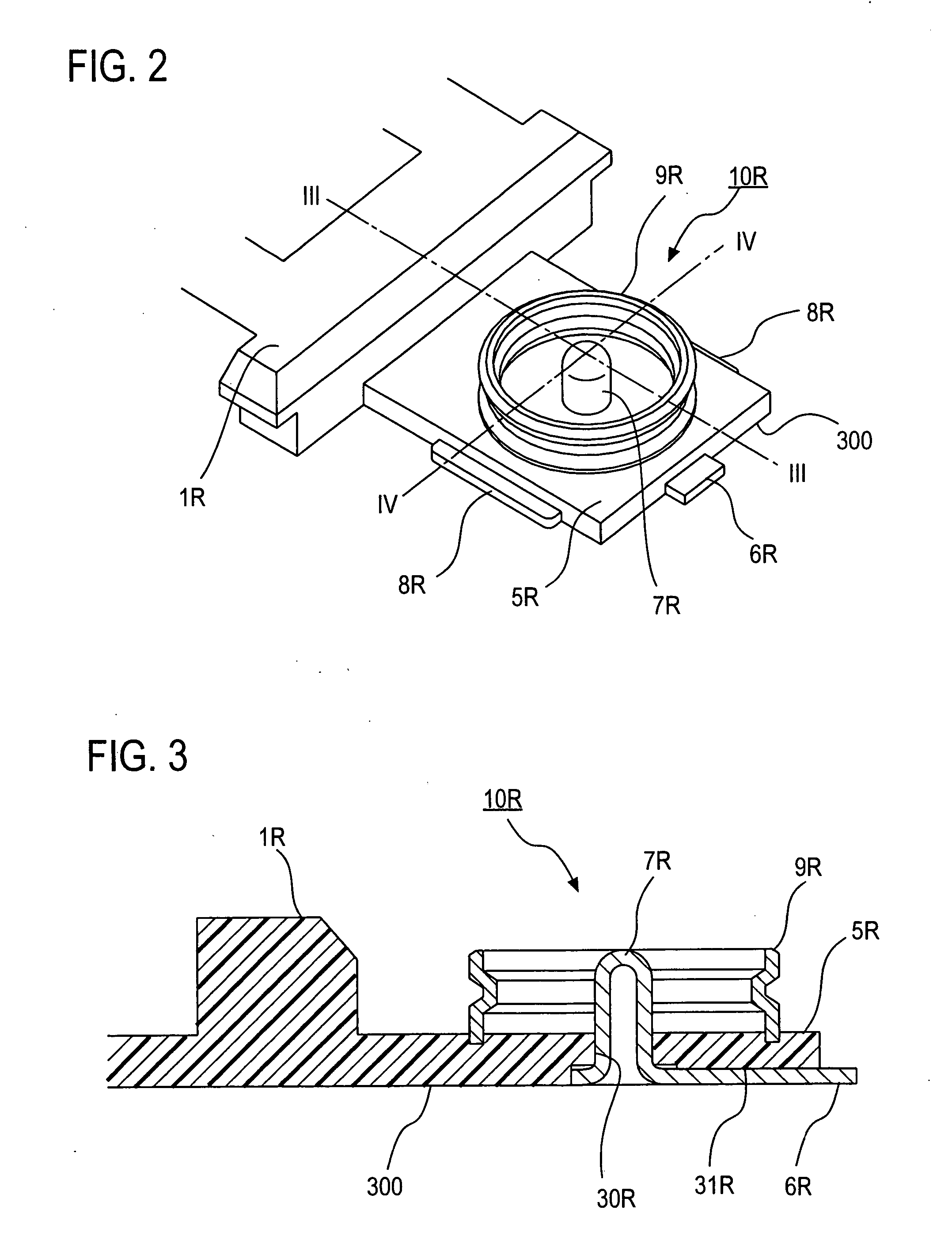
[0038]FIG. 1A is an oblique view of an embodiment of receptacle 100R constituting a connector, of this invention, for integrated board connection of a coaxial connector. Receptacle 100R comprises a nearly parallelepiped shaped multi-connector receptacle 20R and a coaxial receptacle 10R formed integrally at one longitudinal direction end thereof. An insulating housing 1R of multi-connector receptacle 20R forming receptacle 100R is a parallelepiped which has formed therein an insertion recess 2R into which a comp...

second embodiment

2. Second Embodiment

[0091] The contacts of the aforementioned multi-connector part are transmission lines in which characteristic impedances are not taken into account. If the multi-connector also attempts to adapt the characteristic impedances, as described in the prior art, there has been the problem that the whole connector ended up becoming larger in size. Then, there is also a demand of wanting to electro-magnetically shield the multi-connector part, even though there is no need to go to the extent of matching the characteristic impedances. Another embodiment of this invention which responds to this demand is shown in FIGS. 13A, 13B, and 13C, and this invention will be explained further. As for portions explained so far, reference numerals are taken to be the same and an explanation thereof will not be repeated. Explanations are added by means of FIGS. 13A, 13B, and 13C regarding portions for which the structure becomes more clearly defined.

(Structure of the Receptacle of the...


PUM


Abstract

By forming a coaxial receptacle and a coaxial plug, for which the characteristic impedances have been adjusted, at the respective end portions of a receptacle-side insulating housing and a plug-side body constituting a multi-connector being a parallel connector part, a transmission line has been made possible in which a multi-connector is mated and the signals passing through the coaxial connector at the same time exhibit little reflection and radiation.

Description

TECHNICAL FIELD [0001] This invention pertains to a connector for board connection integrally forming a multi-connector, provided with a number of contactors and connecting two boards, and a coaxial connector having a desired characteristic impedance. BACKGROUND ART [0002] As multi-connectors used in signal communication requiring impedance matching between boards, there is known one in which transmission lines are given a strip-line configuration by means of four-layer boards (Non-Patent Reference: Hirose Electric Co., Ltd., ITI Series Product Catalog). In case there are a number of signals requiring impedance matching (below, also called antenna signals or high-frequency signals), this type of connector is used. However, for signals communicating between boards, if e.g. a mobile phone is cited as an example, it is generally the case where the number of high-frequency signals requiring impedance matching is smaller than that of signals for which matching may be ignored. E.g., for a...

Claims


Application Information

Patent Timeline
Patent Type & Authority Applications(United States)
IPC IPC(8): H05K1/00
CPCH01R24/50H01R2103/00H01R2201/02H01R12/716H01R2201/16H01R12/71H01R9/05
Inventor SHICHIDA, AKIHITOIMAI, TORUNAGATA, TAKAYUKI
Owner HOSIDEN CORP
Why Eureka
Try Eureka