Memory device, memory managing method and program

a memory management and memory device technology, applied in the direction of memory adressing/allocation/relocation, instruments, input/output to record carriers, etc., can solve the problems of inefficient frequent flash erase, inability to perform proper data reading and writing, and inability to carry out proper data storage at the manufacturing stage. , to achieve the effect of wasting flash eras

Inactive Publication Date: 2006-06-29
TOKYO ELECTRON DEVICE
View PDF7 Cites 110 Cited by
  • Summary
  • Abstract
  • Description
  • Claims
  • Application Information

AI Technical Summary

Benefits of technology

[0075] Provided that the program discriminates whether or not the number of those memory blocks which do not have data stored therein becomes a number which does not satisfy a predetermined condition (S317), and designates memory blocks from which data is to be erased from among data-storing memory blocks when having discriminated that the number of the memory blocks which do not have data stored therein has become the number which does not satisfy the predetermined condition (S501), data erasure does not take place while there are a sufficient number of empty blocks, so that wasteful flash erase can be avoided.

Problems solved by technology

Of flash memories, particularly, a NAND type has a difficulty in sufficiently preventing the occurrence of defective blocks, which cannot carry out the proper data storage at the manufacturing stage.
In case of rewriting a file whose amount of data is very small as compared with the memory capacity for one block, however, execution of such an operation flash-erases a block that includes lots of pages which store data irrelevant to the file and pages which are not holding data.
While a NAND type flash memory can achieve a large-capacity structure at a low cost, it would be too degraded to perform proper data reading and writing by repetitive flash erase.
That is, executing the aforementioned operation rewrites a small amount of data, which results in inefficient frequent flash erase.
The amount of data in the FAT is normally very smaller than the memory capacity for one block, rewriting the FAT causes inefficient flash erase to be frequently carried out.

Method used


Image

  • Memory device, memory managing method and program
  • Memory device, memory managing method and program
  • Memory device, memory managing method and program

Examples


Embodiment Construction

[0092] One embodiment of the invention will be described below, taking a memory system equipped with a flash memory as an example, with reference to the accompanying drawings.

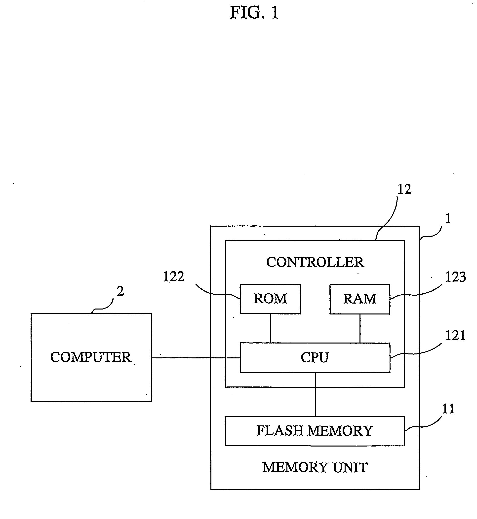
[0093]FIG. 1 is a block diagram illustrating the physical structure of the memory system according to the embodiment of the invention.

[0094] As illustrated, the memory system comprises a memory unit 1 and a computer 2. The memory unit 1 is attached in a detachable manner to the computer 2 via a slot provided in the computer 2.

[0095] The slot of the computer 2 comprises, for example, a PCMCIA slot for relaying a PCMCIA bus.

[0096] The memory unit 1 comprises a flash memory 11 and a controller 12.

[0097] The flash memory 11 is comprised of a memory device, such as EEPROM (Electrically Erasable / Programmable Read Only Memory).

[0098] In response to an access made by the controller 12, the flash memory 11 stores data supplied from the computer 2, supplies stored data to the computer 2 and erases stored data.

[009...


PUM


Abstract

Disclosed is a memory device which is not easily deteriorated and a memory managing method which does not easily deteriorate a memory device. A physical address is given to a memory area of a flash memory (11) page by page. When supplied with to-bewritten data and a logical address where the data is to be written, a CPU (121) writes this data in a page indicated by a write pointer. The correlation between the physical address and the logical address of the page is stored in a RAM (123) in the form of BPT (Block Pointer Table). At the time of reading, the CPU (121) that has been supplied with the logical address searches the BPT to specify a physical address associated with that logical address and reads data from that page which is given the specified physical address. Flash erasing of a block is executed when the number of empty blocks becomes equal to or smaller than a predetermined number.

Description

TECHNICAL FIELD [0001] The present invention relates to a memory device, a memory managing method and a program, and, more particularly, to a block erasure type memory device, and a memory managing method and a program which manage a block erasure type memory device. BACKGROUND ART [0002] An EEPROM (Electrically Erasable / Programmable Read Only Memory) flash memory is used as a recording medium which is accessible (data readable and erasable) by a computer or the like. [0003] A flash memory performs data erasure in the units of a predetermined memory capacity (which are generally called “blocks”). [0004] Of flash memories, particularly, a NAND type has a difficulty in sufficiently preventing the occurrence of defective blocks, which cannot carry out the proper data storage at the manufacturing stage. To cope with the difficulty conventionally, consecutive logical addresses separate from physical addresses allocated to the respective blocks are dynamically allocated to proper blocks a...

Claims


Application Information

Patent Timeline
Patent Type & Authority Applications(United States)
IPC IPC(8): G06F12/00G06F12/10G06F3/06G06F12/02
CPCG06F3/0614G06F3/064G06F3/0679G06F12/0246
Inventor KIKUCHI, SYUICHI
Owner TOKYO ELECTRON DEVICE
Why Eureka
Try Eureka