
Electronic apparatus including disk apparatus

Inactive Publication Date: 2006-06-29
ORION ELECTRIC CO LTD
View PDF10 Cites 13 Cited by
  • Summary
  • Abstract
  • Description
  • Claims
  • Application Information

AI Technical Summary

Benefits of technology

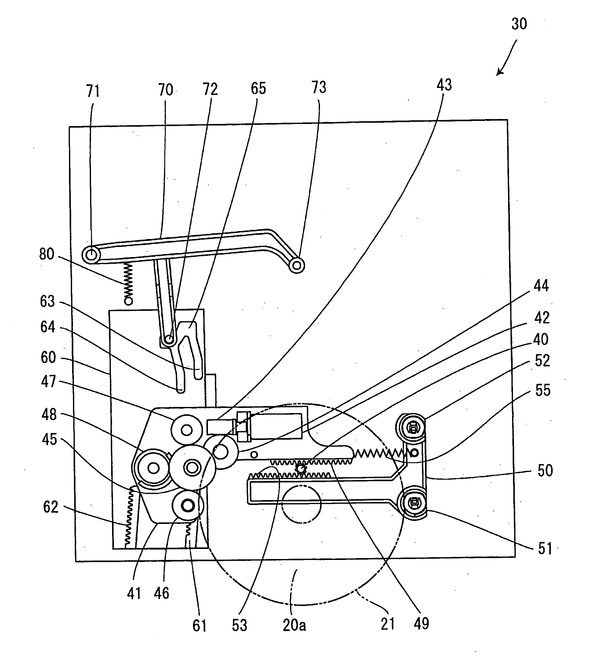
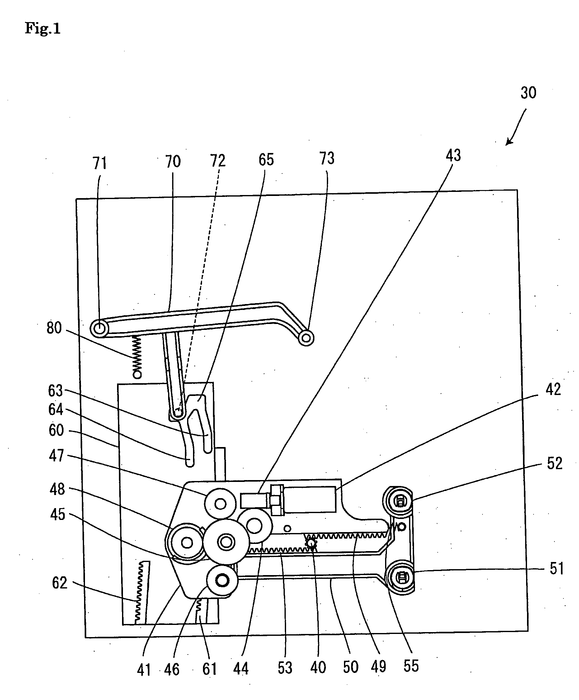
[0012] In the electronic apparatus including the disk apparatus according to the first aspect of the present invention, the rotation rollers can be rotated by the one driving motor arranged on the first base, the relay gears that relay a driving force of the driving motor, and the second gear engaged with the relay gears. The disk-like recording medium can be carried into the disk apparatus while the disk-like recording medium is put between the rotating rotation rollers and the fixed rollers supported by the second base. In addition, the driving force of one driving motor arranged on the first base can drive the slider by engaging the first gear, which is engaged with the second gear, with one of the rack gears provided on the slider. The one driving motor that drives both the rotation rollers and the slider makes it possible to carry the disk-like recording medium and to position the disk-like recording medium by driving the arm using the slider.
[0013] In the electronic apparatus including the disk apparatus according to the second aspect of the present invention, if the disk-like recording medium out of the disk-like recording mediums different in diameter is inserted from the disk inlet and outlet port, the distance between the rotation rollers supported by the first base and the fixed rollers supported by the second base is widened to correspond to anyone of the disk-like recording mediums different in diameter by the interlocking mechanism for moving the first base and the second base in the direction away from each other. Besides, the disk like recording medium can be elastically put between the rotation rollers and the fixed rollers by the urging member that urges the first base and the second base in the direction closer to each other. It is, therefore, possible to stably carry any one of the disk-like recording mediums while putting the disk-like recording medium between the rotation rollers and the fixed rollers.
[0015] In the electronic apparatus including the disk apparatus according to the fourth aspect of the present invention, it is possible to stably position and carry any one of the disk-like recording mediums different in diameter. Further, according to the present invention, the simple mechanical structure enables the disk apparatus to be applicable to both the disk-like recording mediums different in diameter. Therefore, it is unnecessary to use a plurality of motors and a plurality of sensors differently from the conventional techniques, and a cost of the disk apparatus can be reduced by simplifying the structure.

Problems solved by technology

It is, therefore, difficult to directly connect the motor for driving the rotation roller to rotate with the motor for driving the arm for positioning the disks having different outside diameters with a tip end of the arm abutting on the outer circumferential edges of the disks, to rotate, by means of driving force transmission mechanism such as a gear.
Due to this, it is disadvantageously necessary to arrange the first motor for driving the rotation roller for carrying the disk and the second motor for driving the disk positioning arm using the cam mechanism.
In addition, it is disadvantageously necessary to arrange a plurality of the sensor switches for detecting the magnitude and position of each disk, the rotation position of the arm, the longitudinal position of the rack plate, and the like.
According to the latter conventional technique, by configuring the mechanism to be applicable disadvantageously only to the twelve-centimeter disk, the operations from the disk carrying to the disk clamping are driven by one motor.

Method used


Image

  • Electronic apparatus including disk apparatus
  • Electronic apparatus including disk apparatus
  • Electronic apparatus including disk apparatus

Examples


first embodiment

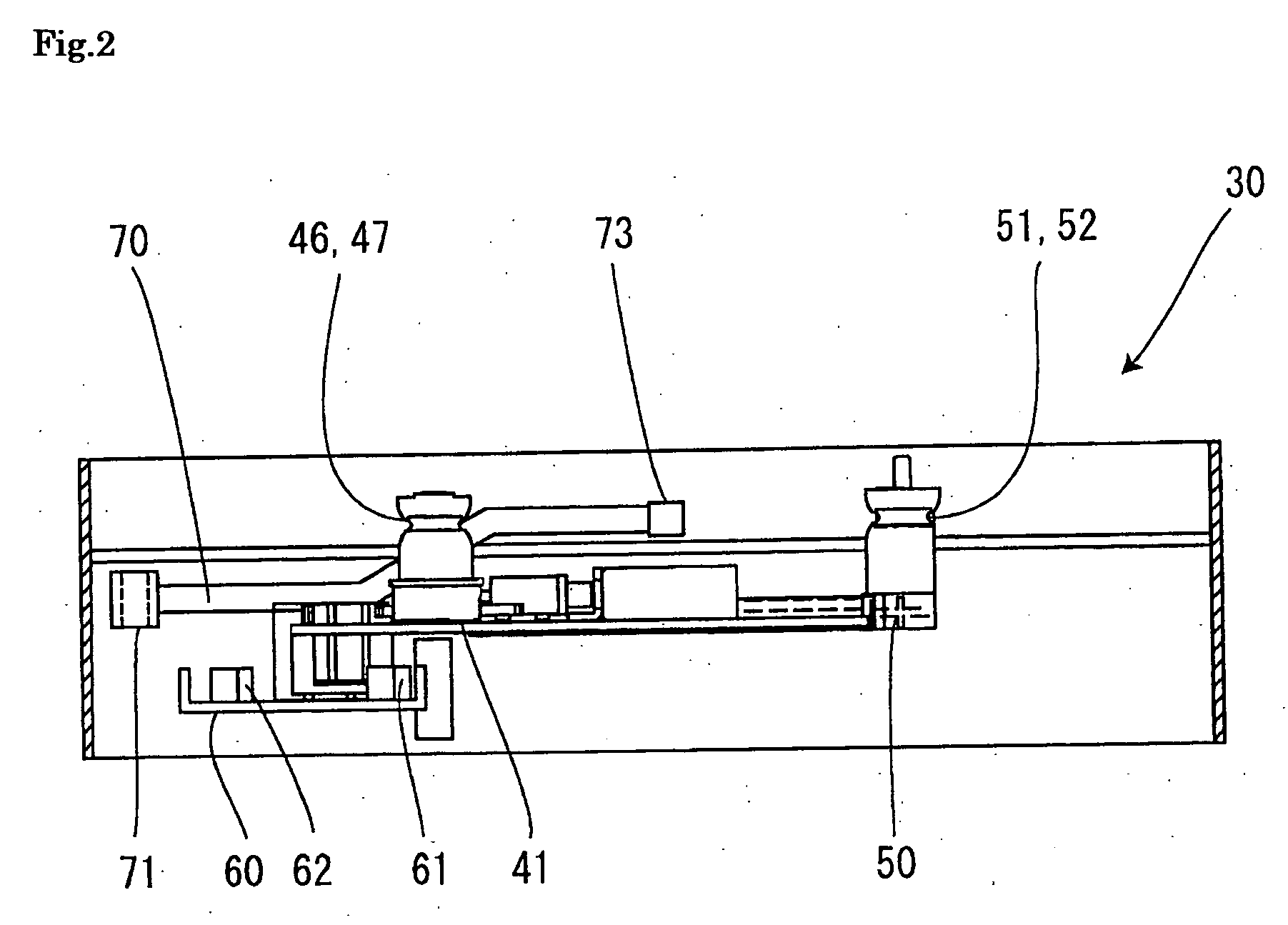
[0036] Referring to FIG. 17, a schematic configuration of a television receiver that includes a DVD disk apparatus will be described. In FIG. 17, a display unit 13 is provided on a front surface 11 of a television receiver 10, a disk inlet and outlet port 15 of a DVD apparatus 30 is provided on a side surface 12 of the television receiver 10, and a DVD disk 20 is about to be inserted into the disk inlet and outlet port 15. The DVD disk apparatus 30 included in this television receiver 10 is a so-called slot-in type disk apparatus configured so that the DVD disk 20 is carried into the DVD disk apparatus 30 by a rotation roller and a fixed roller.

[0037] A schematic configuration of the DVD disk apparatus 30 according to the first embodiment will next be described with reference to FIGS. 1 and 2. FIG. 1 is a perspective plan view that depicts a schematic configuration of a loading mechanism of the DVD disk apparatus 30 included in the television receiver 10 according to the first embo...

second embodiment

[0048] Referring next to FIG. 12, an operation for inserting a twelve-centimeter DVD disk 20b into the disk inlet and outlet port 15 in the same DVD apparatus 30 as that according to the first embodiment, according to a second embodiment will be described. The outer circumferential edge 21 of the twelve-centimeter DVD disk 20b contacts with the first rotation roller 46 and the first fixed roller 51. This state is before a state in which the distance between the first rotation roller 46 and the first fixed roller 51 is to be widened by the insertion operation of the disk 20b. In this state, the first base 41 and the second base 50 are urged by the first spring 55 in the direction in which they are closer to each other, and the driving motor 42 supported by the first base 41 does not start rotation driving yet. Further, the first gear 48 supported by the first base 41 is not engaged yet with any one of the rack gears 61 and 62 formed on the slider 60. The arm 70 is applied with the sp...


PUM


Abstract

A relay gear, a second gear, rotation rollers, and a first gear interlocking with a driving motor are arranged on a first base, and a DVD disk is carried by these rotation rollers and fixed rollers supported by a second base. An arm contacts with an outer circumferential edge of the DVD disk thus carried and is forced rearward. This operation causes a cam arm to move a slider using a cam groove coupling portion of the slider. After positioning the DVD disk, any one of rack gears is engaged with the first gear, whereby the driving motor drives one rotation roller, one fixed roller, and the arm to be separated from the outer circumferential edge of the DVD disk.

Description

BACKGROUND OF THE INVENTION [0001] 1. Field of the Invention [0002] The present invention relates to an electronic apparatus that includes a slot-in type disk apparatus configured so that a disk is carried into the disk apparatus with an outer circumference of the disk put between rollers, and that any one of a disk having an outside diameter of eight centimeters and a disk having an outside diameter of twelve centimeters can be accurately carried and positioned by one loading motor. [0003] 2. Description of the Related Art [0004] Conventionally, as a mechanism for carrying a disk which is a recording medium into a disk apparatus, positioning the disk to a predetermined position, and mounting the disk on a turntable, there is known, for example, “a disk recording and / or reproducing apparatus” disclosed in Japanese Patent Application Laid-Open No. 2002-304798. According to this conventional technique, to carry an eight-centimeter disk or a twelve-centimeter disk using a pair of a rot...

Claims


Application Information

Patent Timeline
IPC IPC(8): G11B17/04G11B17/03
CPCG11B17/0515
Inventor WATANABE, KAZUHIRO
Owner ORION ELECTRIC CO LTD
Learn More