
Guardrail system and associated methods

a guardrail system and guardrail technology, applied in the direction of roads, constructions, building material handling, etc., can solve the problems of inefficient time, high installation cost, and inconvenient installation of temporary guardrails, and achieve the effect of efficient installation

Inactive Publication Date: 2006-07-06
PURVIS HARRISON
View PDF29 Cites 34 Cited by
  • Summary
  • Abstract
  • Description
  • Claims
  • Application Information

AI Technical Summary

Benefits of technology

[0009] In view of the foregoing background, it is therefore an object of the present invention to provide a temporary guardrail system for use on construction sites that can be efficiently installed.
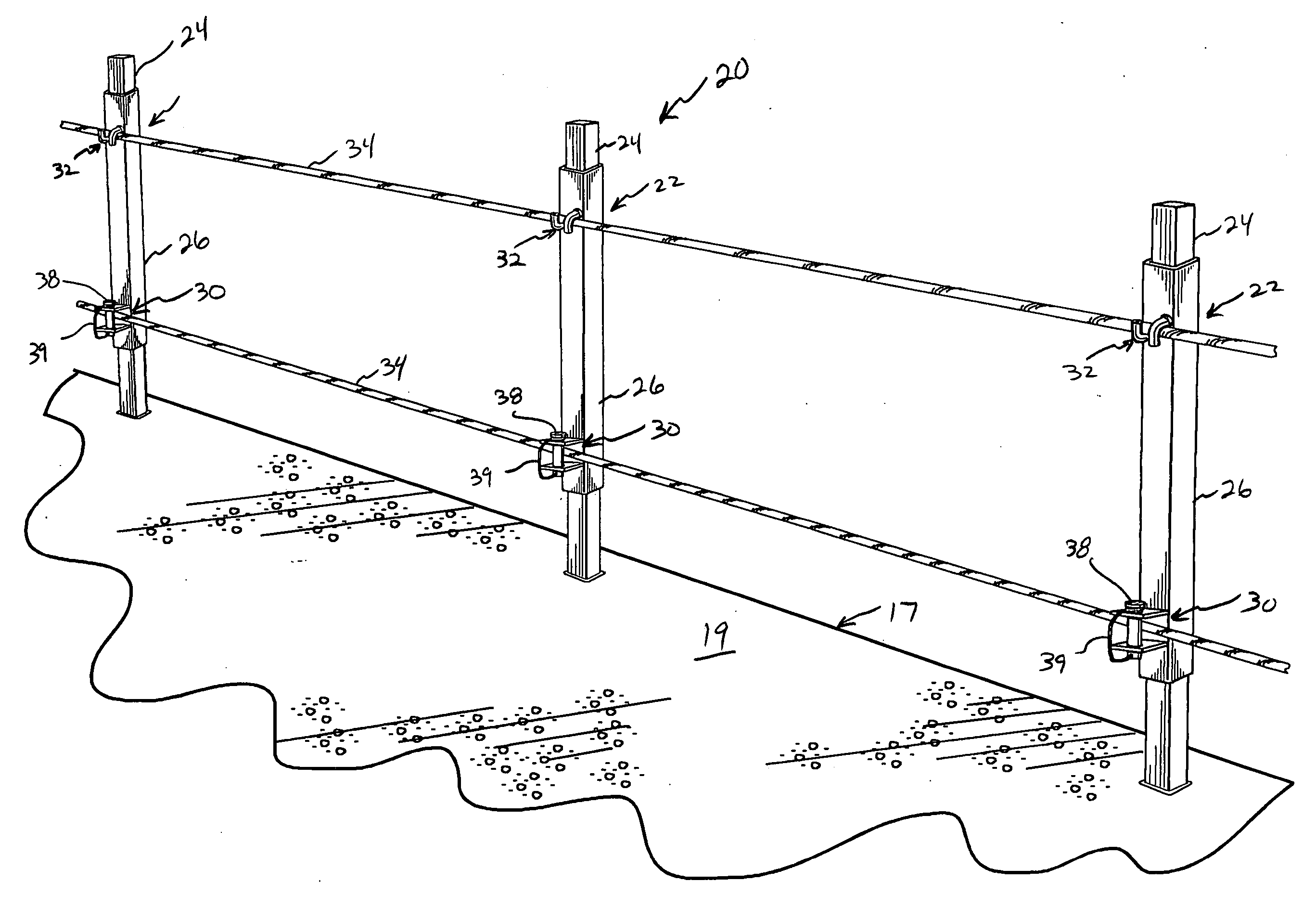
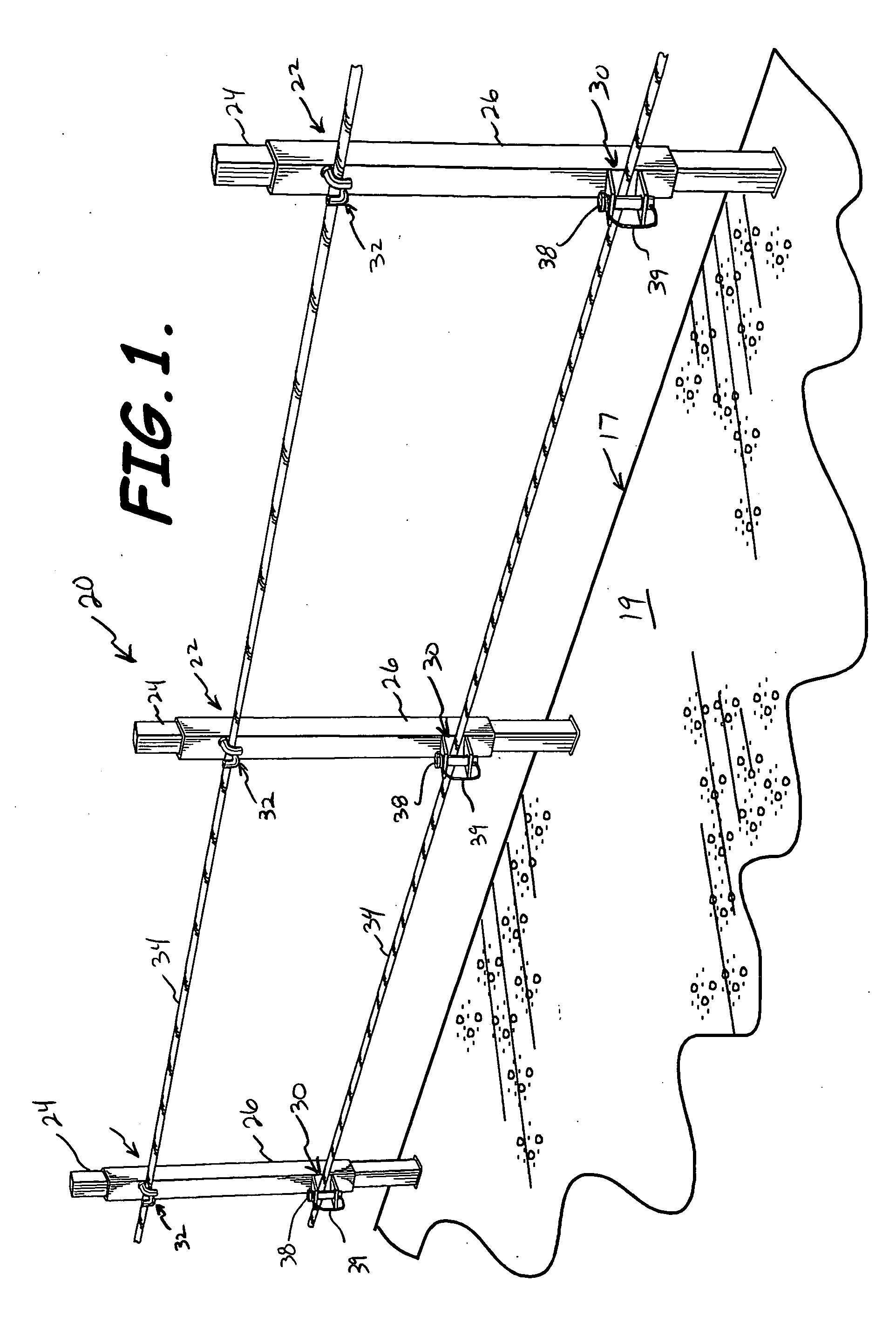
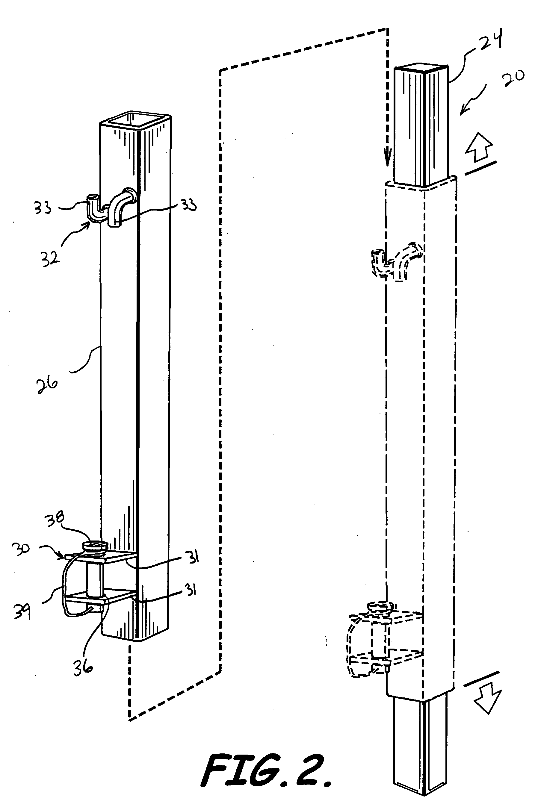
[0017] The guardrail system according to the present invention advantageously allows for simplified installation. More specifically, the rail member may be readily connected to the second cable connector by engaging the rail member between the pair of inverted and opposing J-shaped second cable connector members when the second post member is in a horizontal position. The second post member may then be rotated to a vertical position to retain the cable member between the pair of J-shaped members.

Problems solved by technology

During construction of buildings, both commercial and residential, there has been a problem in providing temporary guardrails adjacent to roof edges, decks, balconies, and even elevated floors prior to the construction of exterior walls.
Although this type of guardrail system may be effective, installation may be expensive, time inefficient, and itself hazardous.
Installation of this guardrail system, however, may be quite time consuming.
Problems with exposed elevated areas of construction still exist.
In fact, these problems are of such a serious nature that the Occupational Hazards Safety Act (OSHA) agency has promulgated regulations to require temporary railings on open elevated building structures that are capable of withstanding at least two hundred pounds of pressure without failing.

Method used


Image

  • Guardrail system and associated methods
  • Guardrail system and associated methods
  • Guardrail system and associated methods

Examples


Embodiment Construction

[0028] The present invention will now be described more fully hereinafter with reference to the accompanying drawings, in which preferred embodiments of the invention are shown. This invention may, however, be embodied in many different forms and should not be construed as limited to the embodiments set forth herein. Rather, these embodiments are provided so that this disclosure will be thorough and complete, and will fully convey the scope of the invention to those skilled in the art. Like numbers refer to like elements throughout, and prime notation is used to indicate similar elements in alternate embodiments.

[0029] Referring initially to FIGS. 1-4, a guardrail system 20 according to the present invention is now described in detail. The guardrail system 20 illustratively includes a plurality of posts 22. The plurality of posts 22 are preferably spaced apart, and positioned adjacent an exposed elevated edge 17 of a flat surface 19, such as a rooftop or balcony under construction,...


PUM


Abstract

A guardrail system includes a plurality of posts and at least one rail member detachably connected to and extending between the plurality of posts. Each of the plurality of posts includes a first post member, and a second post member that slidably engages the first post member. The second post member includes a first cable connector connected to a lower portion thereof, and a second cable connector connected to an upper portion thereof and including a pair of inverted and opposing J-shaped second cable connector members.

Description

RELATED APPLICATIONS [0001] This application claims the benefit of U.S. Provisional Patent Application Ser. No. 60 / 641,385, filed on Jan. 4, 2005, the entire contents of which are incorporated herein by reference.FIELD OF THE INVENTION [0002] The present invention relates to the field of building construction and, more particularly, to the field of temporary guardrail systems for use during construction, and related methods. BACKGROUND OF THE INVENTION [0003] During construction of buildings, both commercial and residential, there has been a problem in providing temporary guardrails adjacent to roof edges, decks, balconies, and even elevated floors prior to the construction of exterior walls. [0004] Temporary guardrails may be constructed adjacent a rooftop with materials commonly found on a construction site, such as excess lumber, for example. A platform is typically built adjacent the edge of the rooftop, and is braced against a wall supporting the rooftop. Spaced-apart guardrail...

Claims


Application Information

Patent Timeline
Patent Type & Authority Applications(United States)
IPC IPC(8): E01F15/00
CPCE04G21/3223E04F2011/1889
Inventor PURVIS, HARRISON
Owner PURVIS HARRISON
Learn More