Stator coil module, method of manufacturing the same, and electric rotating machine

Inactive Publication Date: 2006-07-06
TOYOTA JIDOSHA KK
View PDF9 Cites 42 Cited by
  • Summary
  • Abstract
  • Description
  • Claims
  • Application Information

AI Technical Summary

Benefits of technology

[0031] According to this construction, the electric rotating machine can be constructed by fitting the stator cores into the holes of the stator coil modules and arranging the stator cores in the circumferential direction. Hence,

Problems solved by technology

It is difficult to perform an operation of molding the plate with resin.
Thus, the number of combinations

Method used


Image

  • Stator coil module, method of manufacturing the same, and electric rotating machine
  • Stator coil module, method of manufacturing the same, and electric rotating machine
  • Stator coil module, method of manufacturing the same, and electric rotating machine

Examples


first embodiment

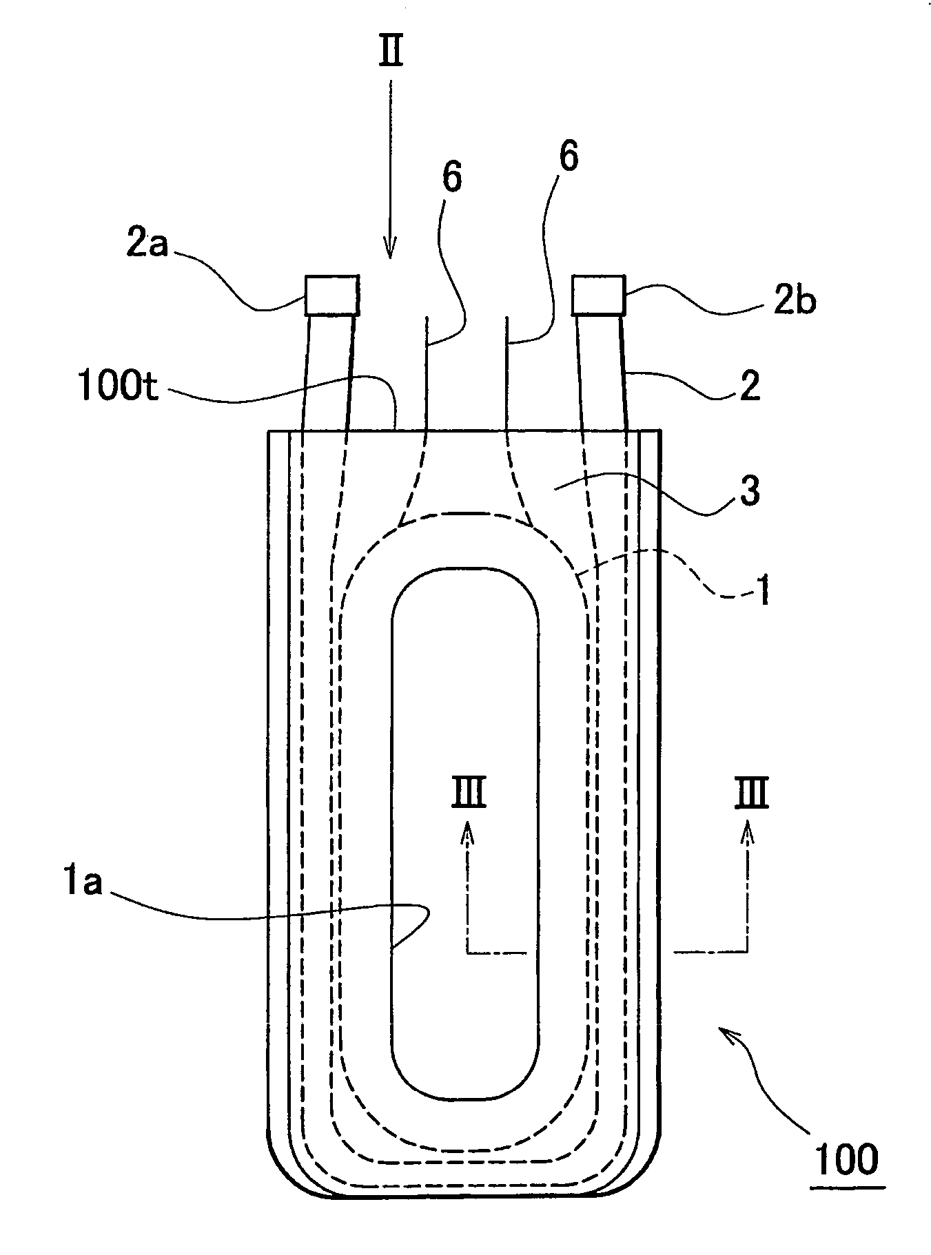
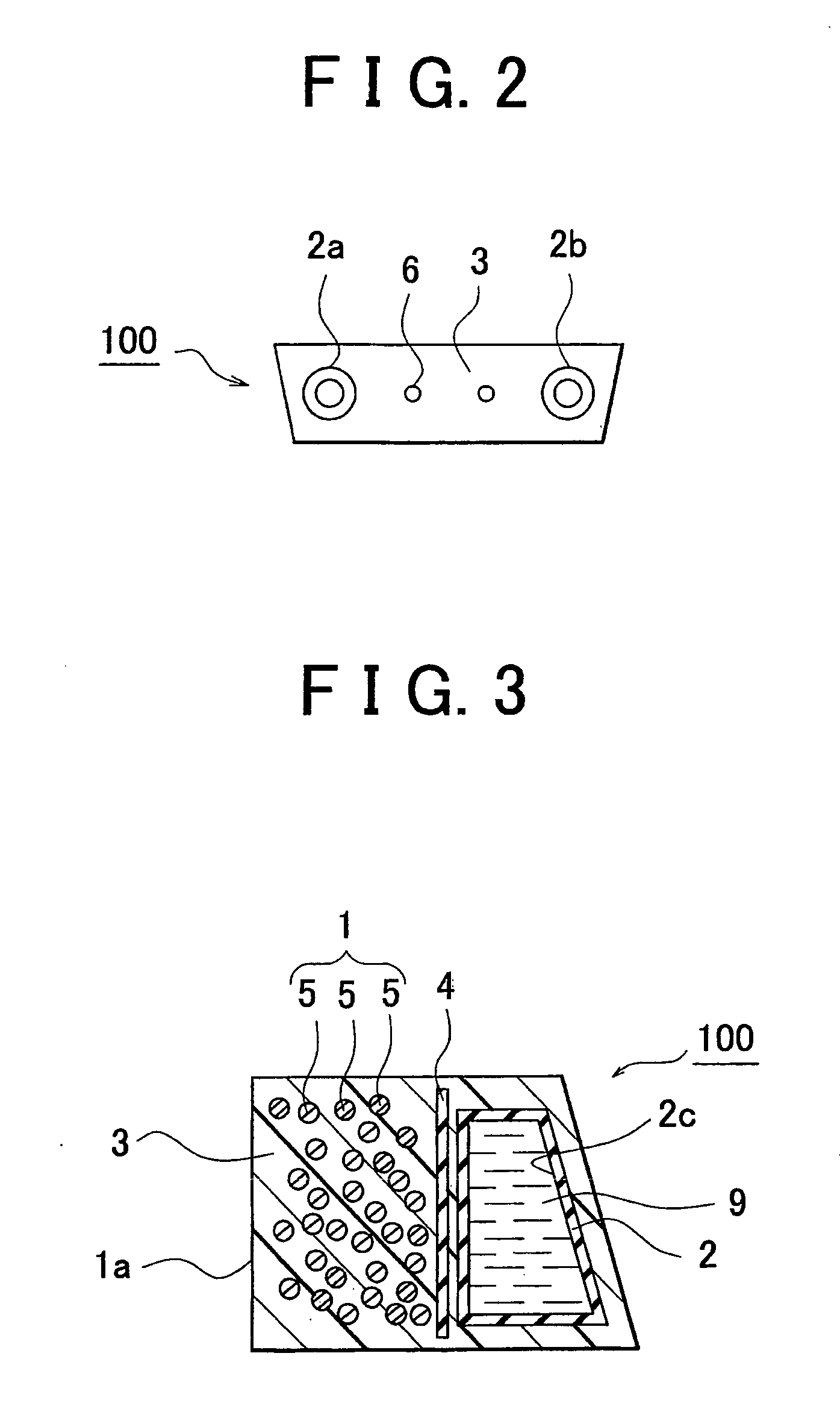
[0051] The construction of a stator coil module 100 in accordance with the invention will be described with reference to FIGS. 1 and 2. The stator coil module 100 is provided with a stator coil 1, a cooling pipe 2, and a mold member 3. The cooling pipe 2 is provided separately from the stator coil 1 and is disposed along it. The mold member 3 serves as an insulating member for molding the stator coil 1 and the cooling pipe 2. A hole 1a surrounded by the stator coil 1 is formed in the mold member 3.

[0052] The stator coil module 100 is further provided with a coil lead wire 6 as a conductive member for supplying the stator coil 1 with electric power. The cooling pipe 2 includes a cooling liquid outlet at one end 2a thereof and a cooling liquid inlet at the other end 2b thereof. The ends 2a and 2b and the coil lead wire 6 are disposed on the side of one end 100t of the stator coil module 100.

[0053] The mold member 3 has a substantially rectangular shape. A hole 1 a is formed in a cent...

second embodiment

[0064] Each of FIGS. 9 and 10 is a cross-sectional view of a stator coil module in accordance with another phase of the aforementioned As shown in FIG. 9, the hole 4a may be formed in the insulator 4. This results in a reduction in thermal resistances of the stator coil 1 and the cooling pipe 2, so that an enhanced cooling capacity is obtained.

[0065] As shown in FIG. 10, there may be no insulator provided between the stator coil 1 and the cooling pipe 2. In this case, owing to a further reduction in the thermal resistances of the stator coil 1 and the cooling pipe 2, an enhanced cooling capacity can be obtained.

[0066] The stator coil module 100 thus constructed in accordance with the second embodiment has substantially the same effect as the stator coil module 100 in accordance with the first embodiment.

[0067] Next, a method of manufacturing the stator coil module in accordance with the first or second embodiment will be described. FIG. 11 shows a process of manufacturing the sta...

third embodiment

[0071] The stator coil module in accordance with the third embodiment may be identical in cross-sectional shape with any one of those shown in FIGS. 3 to 5 and FIGS. 8 to 10.

[0072] In the case where the block 10 is installed, the stator coil 1 and the cooling pipe 2 are integrally molded with resin after the cooling pipe 2 and the coil lead wire 6 have been connected to the block 10 in advance.

[0073] The stator coil module 100 in accordance with the third embodiment has substantially the same effect as the stator coil modules in accordance with the first and second embodiment. In addition, an end face of the block 10, namely, that portion of the block 10 which is in contact with the mold member 3 serves as a sealing face, whereby the moldability of resin molding is enhanced. Because the lead-wire connection ports 11a and 11b and the cooling pipe connection ports 12a and 12b are formed in the block 10, a step of mounting a pipe line and a lead wire is omitted.


PUM


Abstract

A stator coil module facilitating the manufacture of an electric rotating machine is provided. The stator coil module is provided with a stator coil (1), a cooling pipe (2), and a mold member (3). The cooling pipe (2) is provided separately from the stator coil and is disposed along it. The mold member molds the stator coil (1) and the cooling pipe (2). A hole surrounded by the stator coil is formed in the mold member. The cooling pipe includes a coolant outlet (2b) at one end thereof and a cooling inlet at the other end thereof. The stator coil module is further provided with a coil lead wire for supplying the stator coil with electric power. The ends of the cooling pipe and the coil lead wire are disposed on the side of one end of the stator coil module.

Description

BACKGROUND OF THE INVENTION [0001] 1. Field of Invention [0002] The invention relates to a stator coil module, a method of manufacturing the stator coil module, and an electric rotating machine. In particular, the invention relates to an electric rotating machine mounted in a vehicle, a stator coil module employed in the electric rotating machine, and a method of manufacturing the stator coil module. [0003] 2. Description of the Related Art [0004] An art for cooling a stator in an electric rotating machine (a motor, a generator, or a motor-generator) is disclosed, for example, in Japanese Patent Application Laid-Open No. 2002-186211. [0005] In the electric rotating machine disclosed in the aforementioned publication, a plate is provided between segmental cores, and the plate is sealed with resin. It is difficult to perform an operation of molding the plate with resin. [0006] In the electric rotating machine disclosed in the aforementioned publication, a slot serves as a cooling liqu...

Claims


Application Information

Patent Timeline
IPC IPC(8): H02K9/20H02K1/18H02K1/14H02K1/20H02K3/24H02K3/44H02K9/19H02K15/04H02K15/12
CPCH02K1/148H02K3/24H02K15/04H02K15/12H02K2213/12
Inventor WAKITA, TETSUO
Owner TOYOTA JIDOSHA KK
Why Eureka
Try Eureka