Raman probe and Raman spectrum measuring apparatus utilizing the same

a spectrum measuring and raman probe technology, applied in the direction of optical radiation measurement, diagnostics using spectroscopy, instruments, etc., can solve the problems of significant reduction of yield, difficult to obtain a plurality of fibers with identical performance that are necessary for a single probe assembly, and achieve no coupling loss

Inactive Publication Date: 2006-07-06
RIKEN +1
View PDF5 Cites 33 Cited by
  • Summary
  • Abstract
  • Description
  • Claims
  • Application Information

AI Technical Summary

Benefits of technology

The invention provides a structure for connecting optical fibers with filters at the tip of the fiber. The filters are designed to minimize coupling loss and ensure that no light is lost when one fiber is connected to another. Additionally, a thin hard-coat filter is attached to multiple optical fibers to overcome issues related to the thickness of the fibers and the evaporation method. Overall, this invention improves the efficiency and reliability of optical fiber connections.

Problems solved by technology

The technical problem addressed in this patent text is the need for non-invasive medical diagnostic techniques that are more objective and quantitative, particularly in the diagnosis and treatment of arterial sclerosis. The text describes the development of a vascular endoscope for diagnosis, but it is limited in its ability to observe the progress of the symptom. The text also discusses the use of Raman spectroscopic analysis for diagnosis, but optical fibers used in the process can generate interfering light that can lower the signal-to-noise ratio and make measurement impossible. The text describes a solution to this problem by depositing a thin film on the edge surface of the optical fiber to form an interference filter.

Method used


Image

  • Raman probe and Raman spectrum measuring apparatus utilizing the same
  • Raman probe and Raman spectrum measuring apparatus utilizing the same
  • Raman probe and Raman spectrum measuring apparatus utilizing the same

Examples


Embodiment Construction

[0019] The invention will be hereafter described with reference to the drawings.

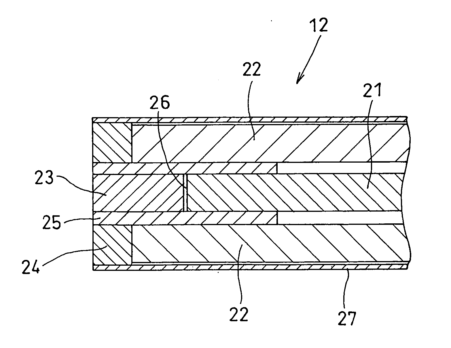
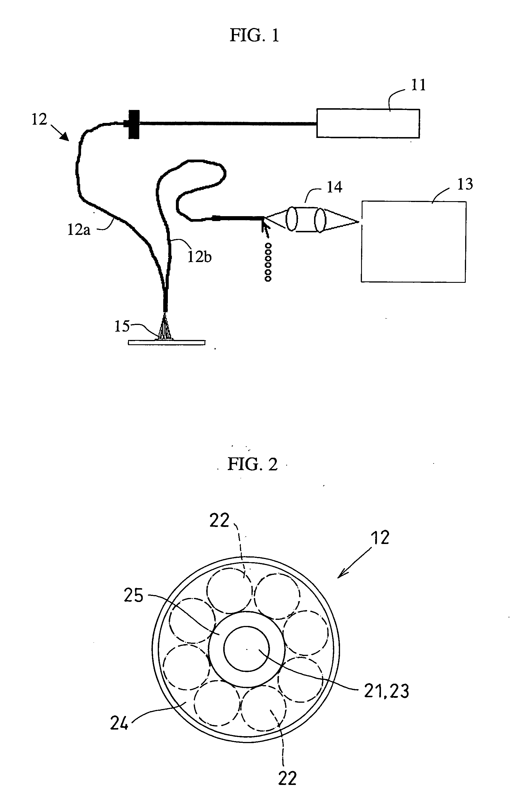
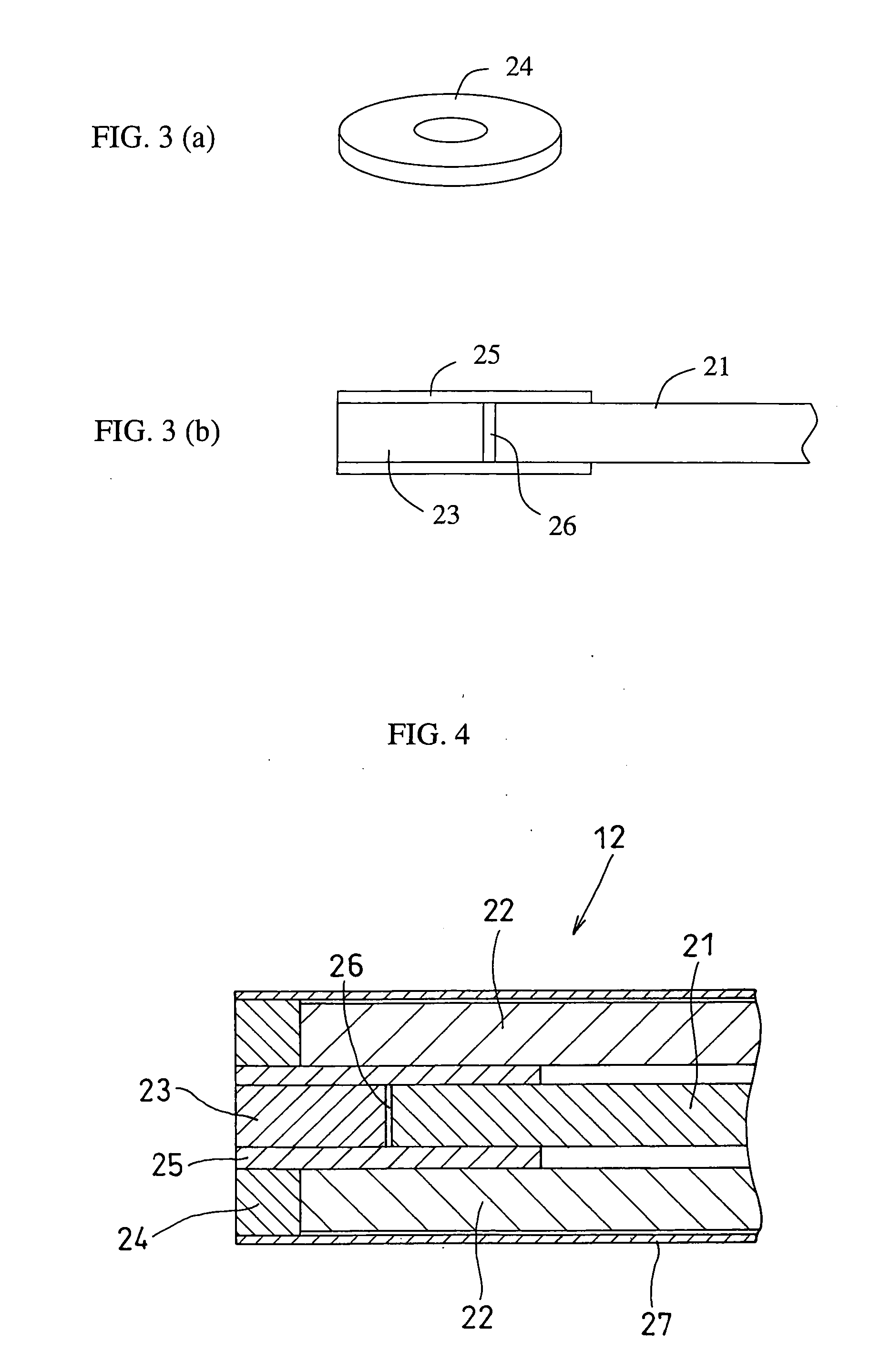
[0020]FIG. 1 schematically shows a Raman spectrum measuring apparatus utilizing a Raman probe according to the invention.

[0021] This Raman spectrum measuring apparatus comprises a laser light source 11 as the excitation light source, a Raman spectrograph 13, and a Raman probe 12 connecting between the excitation light source and a sample 15, and between the sample 15 and the Raman spectrograph 13. The Raman probe 12 comprises an exciting light-guide path 12a and a receiving light-guide path 12b. The exciting-end light guiding path is made up of a single quartz fiber, for example. The receiving light-guide path is made up of a plurality of quartz fibers, for example. In this case, the plural quartz fibers in the receiving light-guide path are arranged in a circle around the exciting quartz fiber on a light-incident end towards the sample. On a light-outgoing end opposite an incident slit of the Raman sp...


PUM


Abstract

A Raman probe that can be used with high-intensity excitation light without producing light that interferes with the measurement of Raman scattering. A receiving-end filter is doughnut-shaped, with an exciting-end filter disposed at the center thereof. A light-blocking structure is provided between the exciting-end filter and the receiving-end filter such that the excitation end and the receiving end are completely separated.

Description


Claims


Application Information

Patent Timeline
Owner RIKEN
Why Eureka
Try Eureka