Opto-electric hybrid board

a hybrid board and optoelectronic technology, applied in the direction of optical elements, circuit optical details, instruments, etc., can solve the problems of low propagation efficiency of light beam l, affecting the accuracy of mounting positions, and lowering productivity, so as to reduce the loss of coupling light

Active Publication Date: 2013-10-03
NITTO DENKO CORP
View PDF4 Cites 13 Cited by
  • Summary
  • Abstract
  • Description
  • Claims
  • Application Information

AI Technical Summary

Benefits of technology

[0014]Preferably, the insulative layer has a light transmittance of not less than 70% at a wavelength of not less than 600 nm. In such a case, a greater amount of light is transmitted through the insulative layer. Thus, the coupling loss of light is decreased.
[0015]Preferably, the insulative layer is a heat-resistant layer having resistance to heat at 150° C. or higher. In such a case, the lens portion is prevented from becoming deformed due to heat produced during the mounting of the optical element. This allows the lens to perform a proper light-gathering effect.

Problems solved by technology

Thus, the light beam L is low in the efficiency of propagation.
However, the lens 60, which is mounted, involves the need for the step of mounting the lens 60, resulting in a problem such that the productivity is lowered.
The process of mounting the lens 60 also results in a problem such that variations occur in the accuracy of the position of the mounting.

Method used


Image

  • Opto-electric hybrid board
  • Opto-electric hybrid board
  • Opto-electric hybrid board

Examples


##ventive examples 1 to 4

Inventive Examples 1 to 4

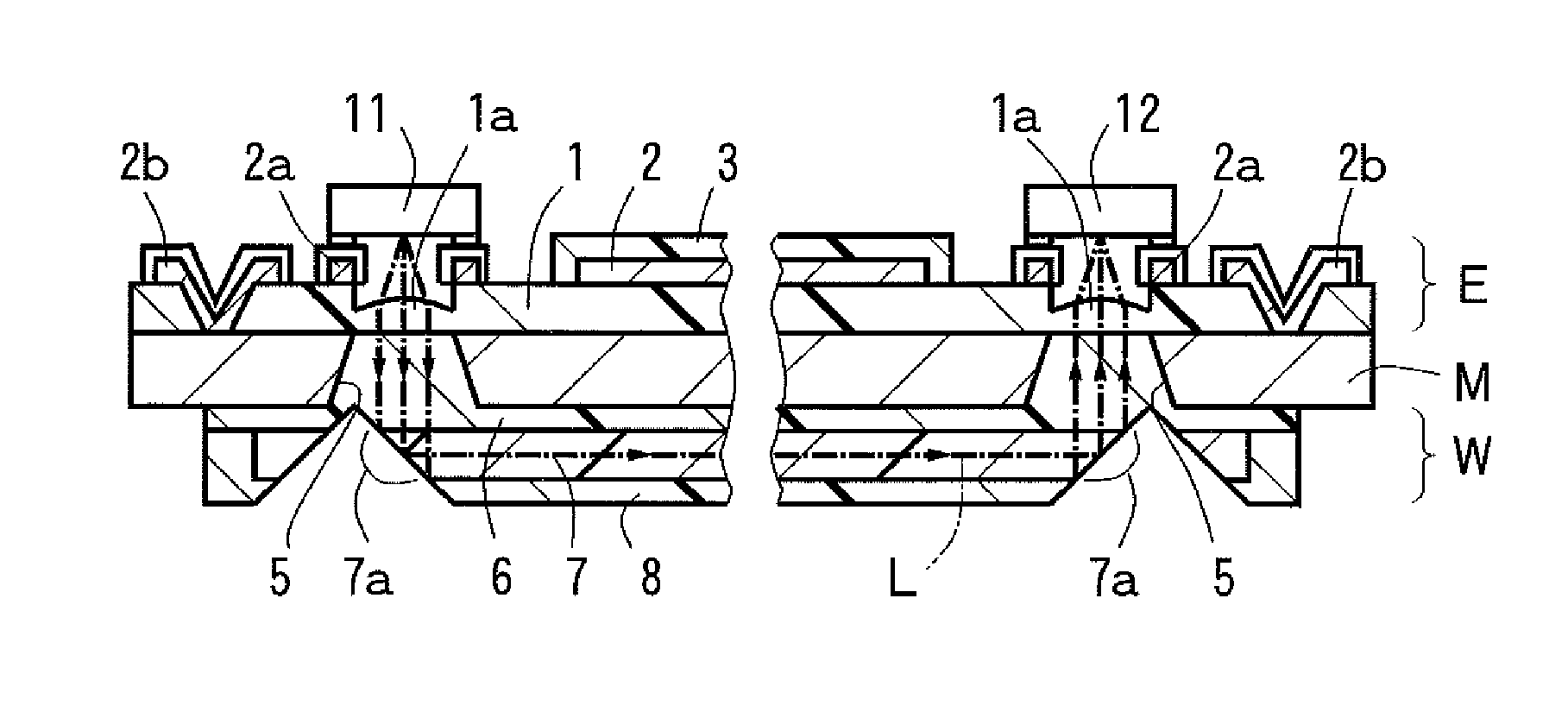
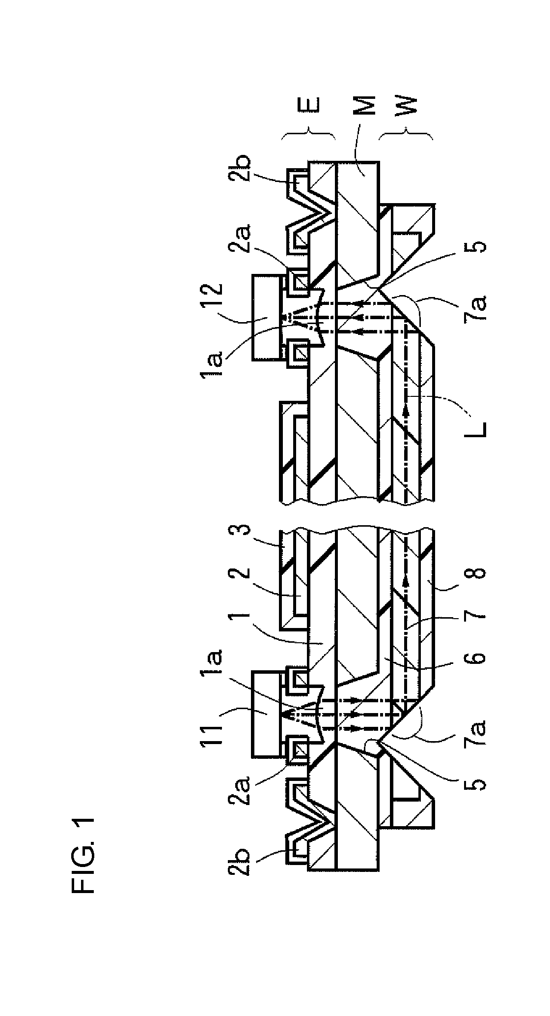
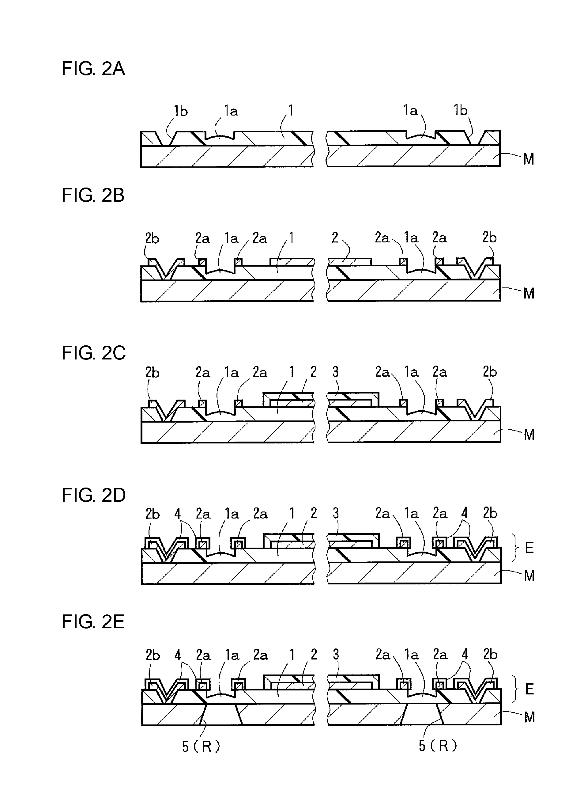
[0059]The opto-electric hybrid board in the first preferred embodiment was prepared as an opto-electric hybrid board in Inventive Example 1, and the opto-electric hybrid board in the second preferred embodiment was prepared as an opto-electric hybrid board in Inventive Example 2. The opto-electric hybrid board in the third preferred embodiment was prepared as an opto-electric hybrid board in Inventive Example 3, and the opto-electric hybrid board in the fourth preferred embodiment was prepared as an opto-electric hybrid board in Inventive Example 4. In each of Inventive Examples 1 to 4, an insulative layer made of a polyimide resin and having lens portions was formed on a front surface of stainless steel foil (SUS304H-TA; a metal layer) having a thickness of 20 μm by a photolithographic process using a photomask. Portions of the photomask corresponding to the lens portions had an average transmittance which was 80% of that of other portions thereof, and the ...


PUM


Abstract

An opto-electric hybrid board includes: an electric circuit board including an insulative layer having front and back surfaces, and electrical interconnect lines formed on the front surface of the insulative layer; an optical element mounted on a surface of the electric circuit board with the electrical interconnect lines formed thereon; and an optical waveguide including a core and formed on the back surface of the insulative layer of the electric circuit board. The core includes at its end portion a reflecting surface capable of reflecting alight beam to propagate the light beam between the core and the optical element. The insulative layer is made of a light-transmissive material. A portion of the insulative layer corresponding to an optical path between the reflecting surface of the core and the optical element is in the form of a lens portion.

Description

BACKGROUND OF THE INVENTION[0001]1. Field of the Invention[0002]The present invention relates to an opto-electric hybrid board in which an electric circuit board with an optical element mounted thereon and an optical waveguide are stacked together.[0003]2. Description of the Related Art[0004]With the increase in the amount of transmission information, optical interconnection in addition to electrical interconnection has been used in recent electronic devices and the like. As an example of such a technique, an opto-electric hybrid board has been disclosed in Japanese Published Patent Application No. 2009-288341. As shown in FIG. 7, this opto-electric hybrid board includes: an electric circuit board E0 including an insulative layer 51, and electrical interconnect lines 52 formed on the front surface of the insulative layer 51; an optical waveguide (optical interconnect lines) W0 (including an under cladding layer 56, cores 57 and an over cladding layer 58) stacked on the back surface ...

Claims


Application Information

Patent Timeline
Patent Type & Authority Applications(United States)
IPC IPC(8): G02B6/36
CPCG02B6/3628G02B6/4283G02B6/4206H05K2201/10121G02B6/43H05K1/0274G02B6/4214G02B6/10H05K1/02G02B6/4204
Inventor TANAKA, NAOYUKIISHIMARU, YASUTO
Owner NITTO DENKO CORP
Why Eureka
Try Eureka