
Optical filtering apparatus and optical communication system

a technology of optical filtering and optical communication system, applied in the direction of electrical apparatus, electromagnetic network arrangement, wavelength-division multiplex system, etc., can solve the problems of increasing the output intensity of optical sources utilized in onus, increasing the service cost, and introducing optical loss, so as to increase the efficiency of tdm-pon

Inactive Publication Date: 2009-06-11
ELECTRONICS & TELECOMM RES INST
View PDF8 Cites 10 Cited by
  • Summary
  • Abstract
  • Description
  • Claims
  • Application Information

AI Technical Summary

Benefits of technology

The present invention provides a method for connecting a large number of subscribers to an OLT on a TDM-PON based on Wavelength Division Multiplexing (WDM), thereby increasing efficiency of the TDM-PON. Additionally, the invention provides a method for minimizing optical loss when combining optical signals transmitted as uplink signals from a plurality of ONUs and transferring the combined signal to an OLT. The invention also includes an optical filtering apparatus and an optical communication system that can reduce coupling loss of uplink signals outputted from a plurality of ONUs on a TDM-PON, and further increase cost efficiency.

Problems solved by technology

However, when a large number of ONUs are connected to an OLT, optical loss is introduced by an optical splitter.
However, increasing the output intensity of optical sources utilized in ONUs is economically inefficient because it increases the service cost per one ONU in proportion to an increase in costs of the ONUs.
Accordingly, in the case of upstream transmission, there is a limit in increasing the optical output intensity.
In this case, optical loss corresponding to optical loss of downstream signals is generated.
In a TDM-PON method in which loss of original signals inevitably occurs, there are difficulties in restoring the original signals through time division multiplexing.
However, enhancing the receiver sensitivity of the optical receiver is very difficult, and reducing optical loss in the conventional TDM-PON also is not easy.

Method used


Image

  • Optical filtering apparatus and optical communication system
  • Optical filtering apparatus and optical communication system
  • Optical filtering apparatus and optical communication system

Examples


Embodiment Construction

[0026]The invention is described more fully hereinafter with reference to the accompanying drawings, in which exemplary embodiments of the invention are shown. This invention may, however, be embodied in many different forms and should not be construed as limited to the exemplary embodiments set forth herein. Rather, these exemplary embodiments are provided so that this disclosure is thorough, and will fully convey the scope of the invention to those skilled in the art. In the drawings, the size and relative sizes of layers and regions may be exaggerated for clarity. Like reference numerals in the drawings denote like elements.

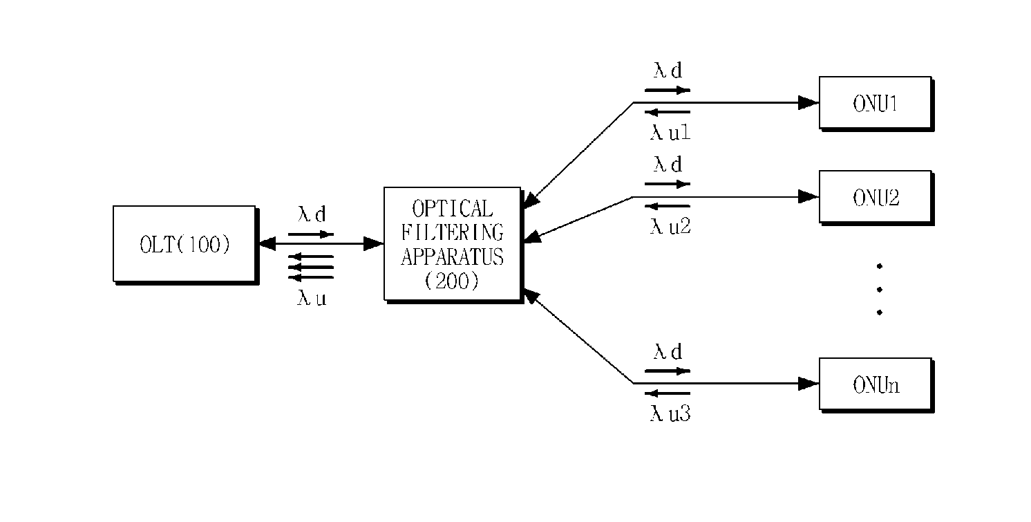
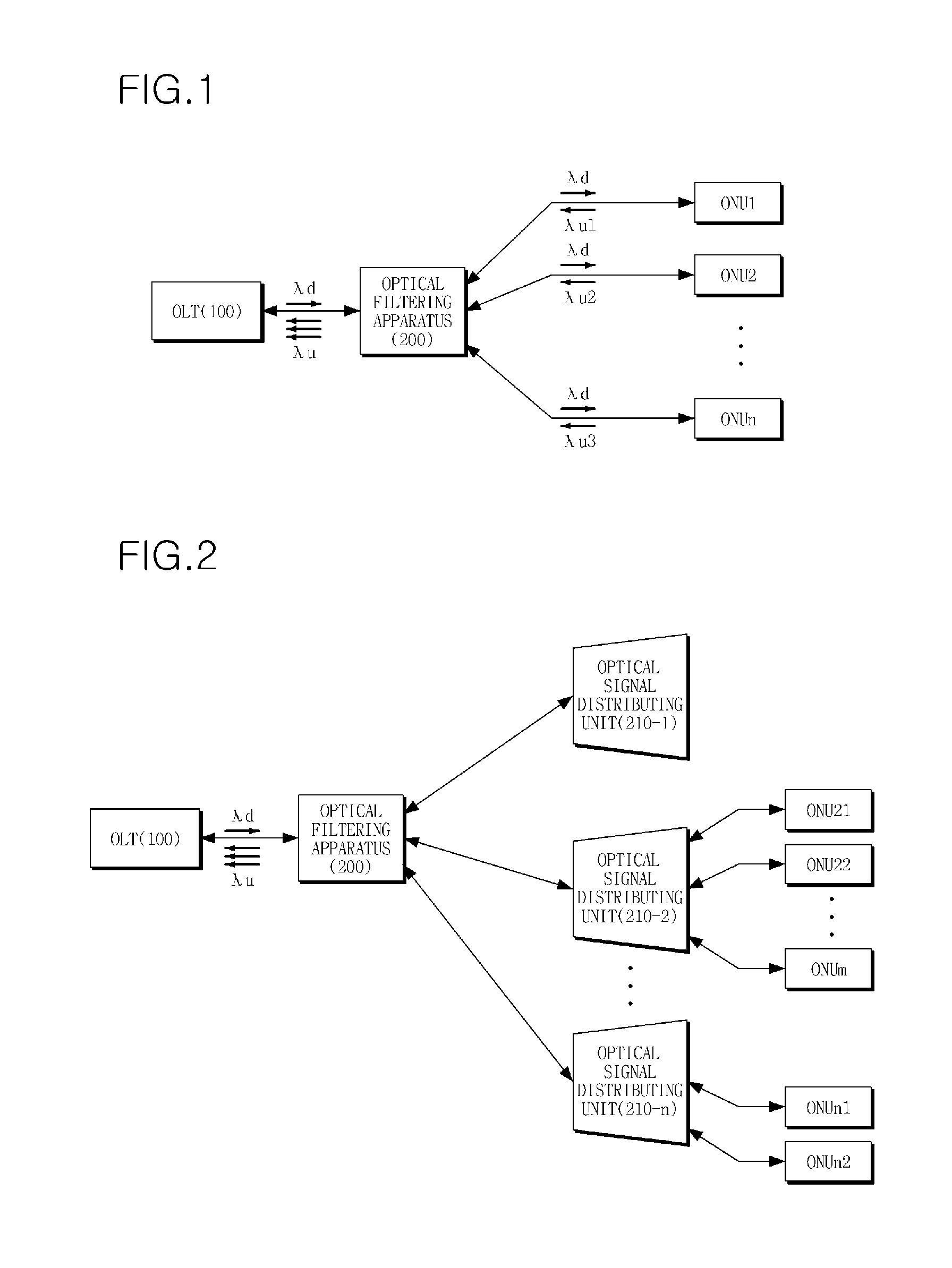
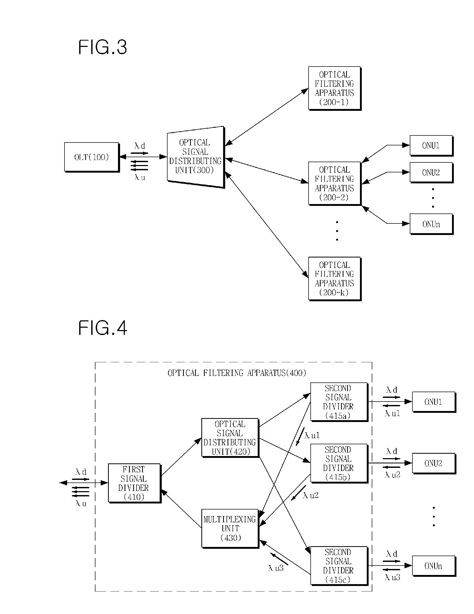
[0027]FIG. 1 is a configuration view of an optical communication system according to an embodiment of the present invention. As illustrated in FIG. 1, the optical communication system includes: an optical line terminal (OLT) 100 including a light source, and at least one communication unit which outputs an optical signal generated by the light source and recei...


PUM


Abstract

Provided is an optical filtering apparatus which is applied to a Time Division Multiplexing Passive Optical Network (TDM-PON) based on a wavelength division multiplexing (WDM) method. The optical filtering apparatus includes: an optical signal distributing unit dividing an optical signal received from an optical line terminal into at least one optical signal with uniform output intensity, and distributing the at least one optical signal into at least one optical network unit; and a multiplexing unit combining a plurality of optical signals having different wavelengths received from the at least one optical network unit using a wavelength division multiplexing (WDM) method, and outputting the combined optical signal to the optical line terminal. Therefore, by using the optical filtering apparatus, it is possible to connect a large number of subscribers to an Optical Line Terminal (OLT) on a network such as Fiber To The Home (FTTH), thereby increasing efficiency in costs.

Description

CROSS REFERENCE TO RELATED APPLICATIONS[0001]This application claims priority from Korean Patent Application No. 10-2007-0125681, filed on Dec. 5, 2007, and Korean Patent Application No. 10-2008-0025864, filed on Mar. 20, 2008, the disclosures of which are incorporated herein in their entireties by reference.BACKGROUND OF THE INVENTION[0002]1. Field of the Invention[0003]The present invention relates to an optical filtering apparatus, and more particularly, to an optical filtering apparatus which is used in a Time Division Multiplexing-based Passive Optical Network (TDM-PON) to which wavelength division multiplexing (WDM) is applied.[0004]2. Description of the Related Art[0005]In a Time Division Multiplexing Passive Optical Network (TDM-PON), a plurality of optical network units (ONUs) are connected to an optical line terminal (OLT).[0006]The plurality of ONUs share the OLT including an optical source and an optical transceiver and optical lines. Accordingly, the ONUs can share cost...

Claims


Application Information

Patent Timeline
Patent Type & Authority Applications(United States)
IPC IPC(8): H04J14/02H04B10/272H04B10/27H04J14/00
CPCH04J14/0226H04J14/0227H04J14/0282H04Q11/0067H04J14/0252H04Q2011/0096H04J14/0247H04J14/025H04Q2011/0015
Inventor KIM, BONG-KYUYOON, BIN-YEONGHAN, YOUNG-TAKKWON, YOOLKIM, BONG-TAE
Owner ELECTRONICS & TELECOMM RES INST
Learn More