Integrated semiconductor optical device
a semiconductor and optical device technology, applied in the direction of instruments, light demodulation, optical waveguide light guides, etc., can solve the problems of increasing the device length, complicating the processing process, and causing so as to suppress the coupling loss of guided light and suppress the output of emitted light
- Summary
- Abstract
- Description
- Claims
- Application Information
AI Technical Summary
Benefits of technology
Problems solved by technology
Method used
Image
Examples
first embodiment
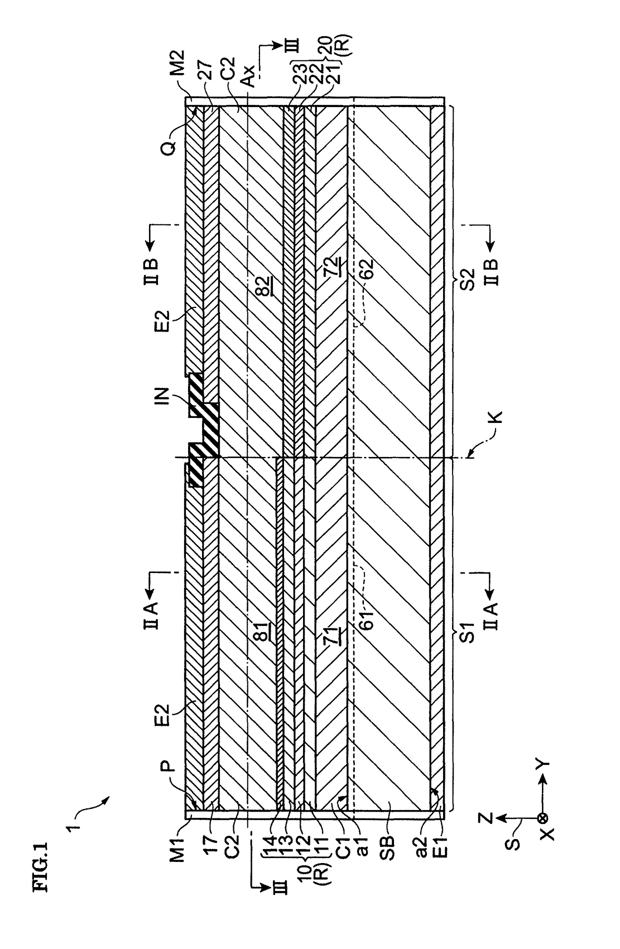
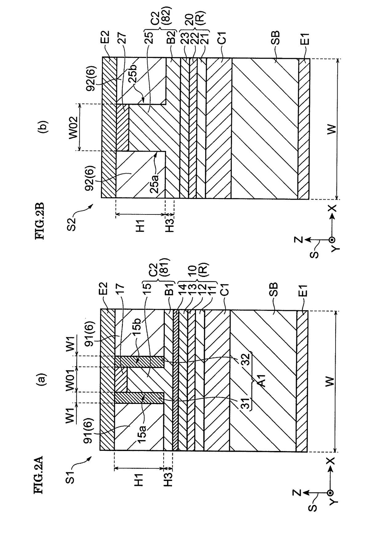
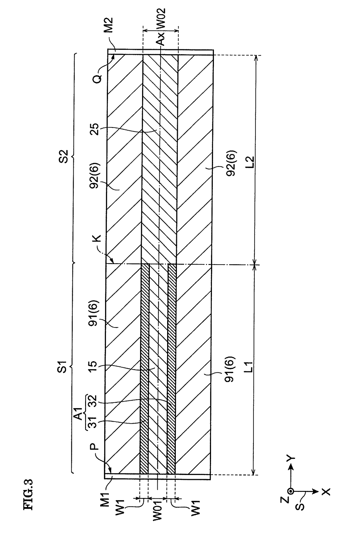
[0043]FIG. 1 is a sectional view schematically illustrating an integrated semiconductor optical device 1. FIG. 2A is a sectional view taken along line IIA-IIA in FIG. 1. FIG. 2B is a sectional view taken along line IIB-IIB in FIG. 1. FIG. 3 is a sectional view taken along line III-III in FIG. 1.
[0044]Referring to FIG. 1, the integrated semiconductor optical device 1 includes a first semiconductor optical device S1 and a second semiconductor optical device S2. The first semiconductor optical device S1 is, for example, a semiconductor light emitting device such as a distributed feedback (DFB) laser diode. The second semiconductor optical device S2 is, for example, an electro-absorption (EA) optical modulator. The first semiconductor optical device S1 and the second semiconductor optical device S2 are optically joined together at a joint boundary K by a butt joint method.
[0045]In the integrated semiconductor optical device 1, the first semiconductor optical device S1 and the second sem...
second embodiment
[0104]Hereinafter, an integrated semiconductor optical device according to a second embodiment will be described with reference to FIGS. 14A, 14B, 15, and 16A to 16D. FIGS. 14A and 14B are sectional views illustrating a modification of the configurations in FIGS. 2A and 2B. FIG. 15 is a sectional view illustrating a modification of the configuration in FIG. 3. FIGS. 16A to 16D illustrate examples of a beam intensity distribution of guided light. The only difference of the integrated semiconductor optical device according to the second embodiment from the integrated semiconductor optical device 1 according to the first embodiment is an adjusting layer. Thus, descriptions other than the adjusting layer are omitted.
[0105]Referring to FIG. 14A, like the first semiconductor optical device S1 according to the first embodiment, the first semiconductor optical device S1 according to the second embodiment includes the first adjusting layer A1. Referring to FIG. 14B, unlike the second semicon...
third embodiment
[0121]Hereinafter, an integrated semiconductor optical device according to a third embodiment will be described with reference to FIGS. 17A, 17B, and 18. FIGS. 17A and 17B are sectional views illustrating a modification of the configurations in FIGS. 2A and 2B. FIG. 18 is a sectional view illustrating a modification of the configuration in FIG. 3. The only differences of the integrated semiconductor optical device according to the third embodiment from the integrated semiconductor optical device according to the first embodiment are adjusting layers. Thus, descriptions other than the adjusting layers are omitted.
[0122]Referring to FIG. 17A, a first semiconductor optical device S13 of the integrated semiconductor optical device according to the third embodiment includes a third adjusting layer A3 in addition to the first adjusting layer A1. The third adjusting layer A3 includes a fifth portion 35 and a sixth portion 36 that extend in the direction of the predetermined axis Ax. The fi...
PUM
| Property | Measurement | Unit |
|---|---|---|
| widths W1 | aaaaa | aaaaa |
| length | aaaaa | aaaaa |
| length | aaaaa | aaaaa |
Abstract
Description
Claims
Application Information
 - R&D
- Intellectual Property
- Life Sciences
- Materials
- Tech Scout
- Unparalleled Data Quality
- Higher Quality Content
- 60% Fewer Hallucinations
Browse by: Latest US Patents, China's latest patents, Technical Efficacy Thesaurus, Application Domain, Technology Topic, Popular Technical Reports.
© 2025 PatSnap. All rights reserved.Legal|Privacy policy|Modern Slavery Act Transparency Statement|Sitemap|About US| Contact US: help@patsnap.com


