
Led backlight apparatus

Inactive Publication Date: 2006-07-06
SAMSUNG ELECTRO MECHANICS CO LTD
View PDF16 Cites 29 Cited by
  • Summary
  • Abstract
  • Description
  • Claims
  • Application Information

AI Technical Summary

Benefits of technology

[0015] The present invention has been made to solve the foregoing problems of the prior art and it is therefore an object of the present invention to provide an LED backlight apparatus having LED light sources arranged opposite to a reflective sheet so that light beams emitted from the LED light sources are reflected from the reflective sheet and then introduced into a diffuser plate placed behind the LED light sources, thereby to reduce the thickness of the backlight apparatus while ensuring a space sufficient for the light beams to mix together before entering the diffuser plate.
[0016] It is another object of the invention to provide an LED backlight apparatus having a projection formed on a reflective sheet opposed to LED light sources to mixing light beams emitted from the LED light sources more uniformly while preventing any loss of the light beams.
[0017] It is further another object of the invention to provide an LED backlight apparatus having intermediate projections formed on a reflective sheet corresponding to areas each intermediating between adjacent LED light sources so that light beams emitted from the LED light sources are reflected upward mostly from areas between adjacent intermediate projections, thereby to prevent wide spreading of light and thus to enhance brightness.
[0018] It is yet another object of the invention to provide an LED backlight apparatus having intermediate projections extended up to a height adjacent to a diffuser plate so that light beams emitted from a group of LEDs between adjacent intermediate projections are introduced into a corresponding area of the diffuser plate, thereby to further enhance brightness.

Problems solved by technology

However, this structure is not applicable to a large-sized LCD since light from the LED light sources 18 and 20 can be sent to a limited distance only.
However, the backlight apparatus 30 of this structure disadvantageously increases thickness since a gap G1 is required between the LED light sources 34 and the transparent plate 38 and a gap G2 is also required between the transparent plate 38 and the diffuser plate 40.

Method used


Image

  • Led backlight apparatus
  • Led backlight apparatus
  • Led backlight apparatus

Examples


Embodiment Construction

[0046] A preferred embodiment of the present invention will now be described in detail with reference to the accompanying drawings.

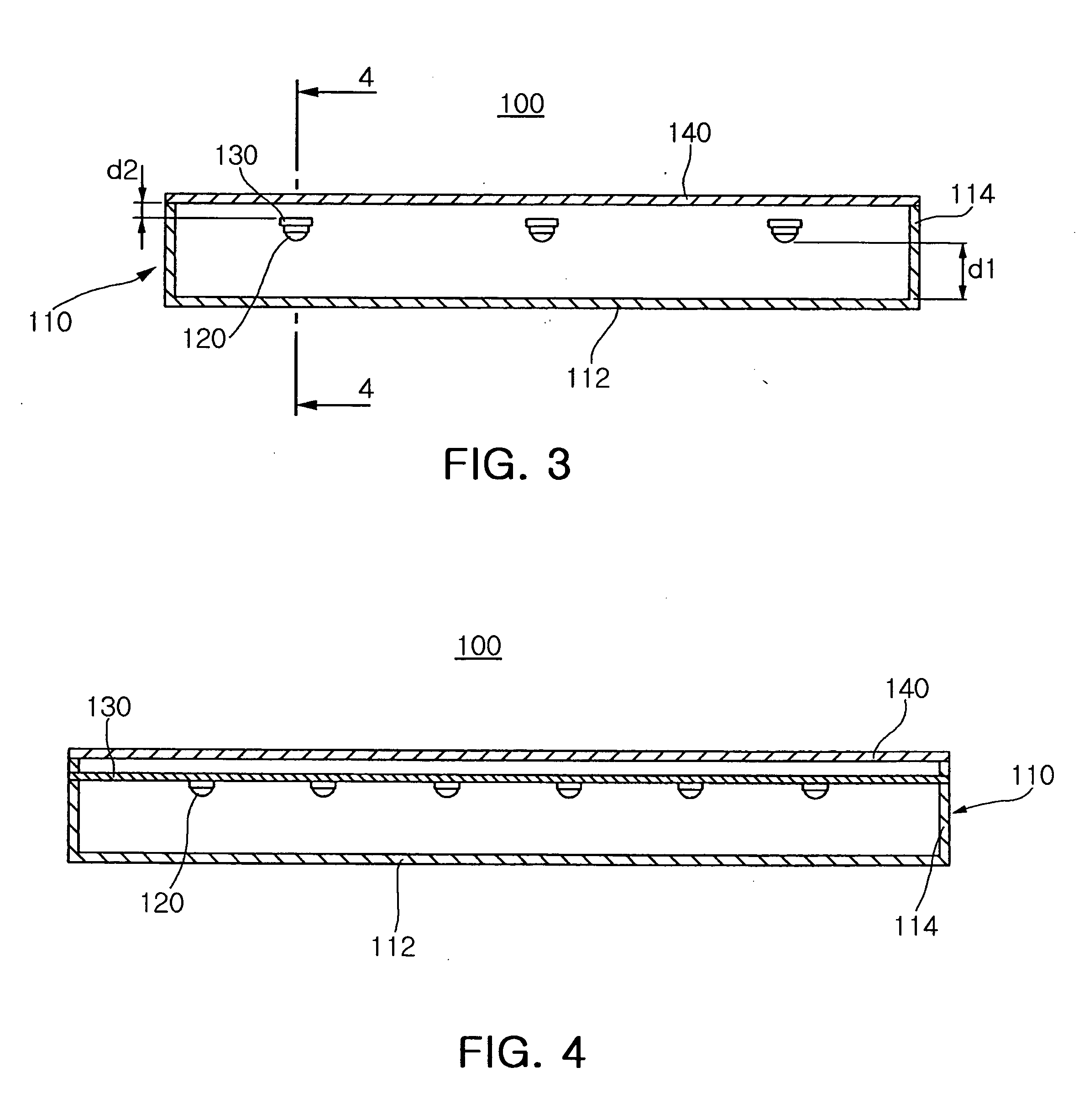
[0047]FIG. 3 is a front cross-sectional view of an LED backlight apparatus 100 according to a first embodiment of the invention, FIG. 4 is a side cross-sectional view taken along the line 4-4 of FIG. 3, and FIG. 5 is an exploded perspective view of the backlight apparatus shown in FIG. 3.

[0048] Referring to FIGS. 3 to 5, the backlight apparatus according to the first embodiment of the invention includes a housing 110 having an upper opening, a plurality of LEDs 120 placed within the housing 110 adjacent to the opening and bar-shaped PCBs 130 connected to side walls 114 of the housing 110 and functioning as a bracket to support the LEDs 120. Besides, a diffuser plate 140 is placed over the opening of the housing 110.

[0049] The housing 110 is hollow to receive the LEDs 120 and the PCBs 130, and has a reflective sheet 112 placed in the bottom. The side w...


PUM


Abstract

This invention relates to an LED backlight apparatus. The LED backlight apparatus comprises: a housing having an upper opening; a reflective sheet provided on a bottom inside the housing; a plurality of LED light sources arranged above the reflective sheet at a predetermined distance to emit light toward the reflective sheet; and a light source support connected to a side wall of the housing to support the LED light sources. The light sources are arranged opposite to the reflective sheet so that light beams emitted from the LED light sources reflect from the reflective sheet before entering a diffuser plate behind the LED light sources from the reflective sheet, thereby potentially reducing the thickness of the backlight apparatus while ensuring a distance for the light beams to sufficiently mix together before entering the differ plate.

Description

CLAIM OF PRIORITY [0001] This application claims the benefit of Korean Patent Application No. 10-2004-0116279 filed on Dec. 30, 2004, in the Korean Intellectual Property Office, the disclosure of which is incorporated herein by reference. BACKGROUND OF THE INVENTION [0002] 1. Field of the Invention [0003] The present invention relates to a backlight apparatus having Light Emitting Diodes (LEDs), and more particularly, in which LED light sources are arranged opposite to a reflective sheet so that light beams emitted from the LED light sources reflect from a reflective sheet before entering a diffuser plate behind the LED light sources, thereby potentially reducing the thickness of the backlight apparatus while ensuring a distance for the light beams to sufficiently mix together before entering the differ plate. [0004] 2. Description of the Related Art [0005] LCD backlight apparatuses using Light Emitting Diodes (LEDs) illuminate an LCD panel via direct illumination or side-emitting i...

Claims


Application Information

Patent Timeline
IPC IPC(8): F21V7/00
CPCG02F1/133603G02F1/133605G02F1/1335
Inventor PARK, JUNG KYUHAHM, HUN JOOAHN, HO SIKKIM, BUM JINPARK, YOUNG SAMKIM, HYUNG SUKJEONG, YOUNG JUNE
Owner SAMSUNG ELECTRO MECHANICS CO LTD
Learn More