
Sunset timer

a timer and sunset technology, applied in the field of sunset timers, can solve the problems of timers that cannot be accurately set to automatically activate or deactivate light fixtures at sunrise and sunset times for all states within a given geographic zone, timers that will have to be reset periodically, and process is tedious, etc., to achieve the effect of convenient use and convenient s

Inactive Publication Date: 2006-07-06
HARDWARE INNOVATIONS
View PDF57 Cites 70 Cited by
  • Summary
  • Abstract
  • Description
  • Claims
  • Application Information

AI Technical Summary

Benefits of technology

[0009] It is still a further object of the present invention to pre-program a timer with sunrise and sunset information for various geographic locations which can be selected and easily set by a user through the use of the aforementioned indicator of geographic location.
[0010] It is yet another object to the present invention to provide an easy to use means of inputting the geographic location into the timer.

Problems solved by technology

This can be done manually, however, the disadvantage of having to manually set a timer is that the timer will have to be reset periodically in order to adapt the timer to the change in sunset time.
While potentially useful in some regions of the U.S., this prior art timer cannot be accurately set to automatically activate or deactivate light fixtures at the sunrise and sunset times for all states within a given geographic zone.
Moreover, while a user can manually set the prior art timer to coincide with sunset and sunrise times for a particular geographic region, such process is tedious and does not include the advantages inherent to an automated system.
However, there is no specific teaching as to how the latitude and longitude information is correlated to sunrise / sunset times. Moreover, while the feeder is pre-programmed with default settings for latitude and longitude information, the user must change this information in the feeder to conform to his or her geographic location.
As a practical matter, users would not typically know this information and would not be able to set the feeder to accurately operate in conjunction with local sunset and sunrise times.

Method used


Image

  • Sunset timer
  • Sunset timer
  • Sunset timer

Examples


Embodiment Construction

)

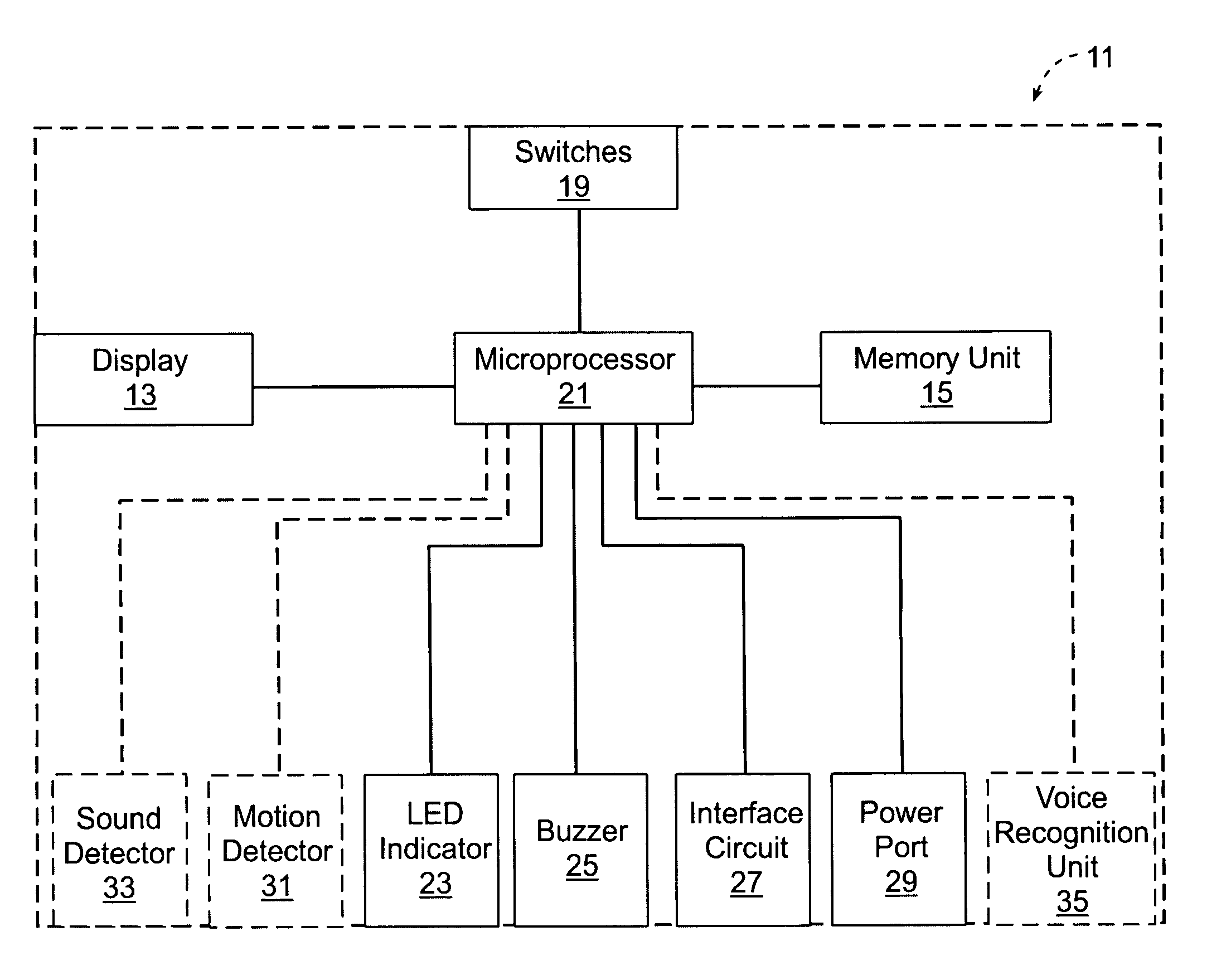
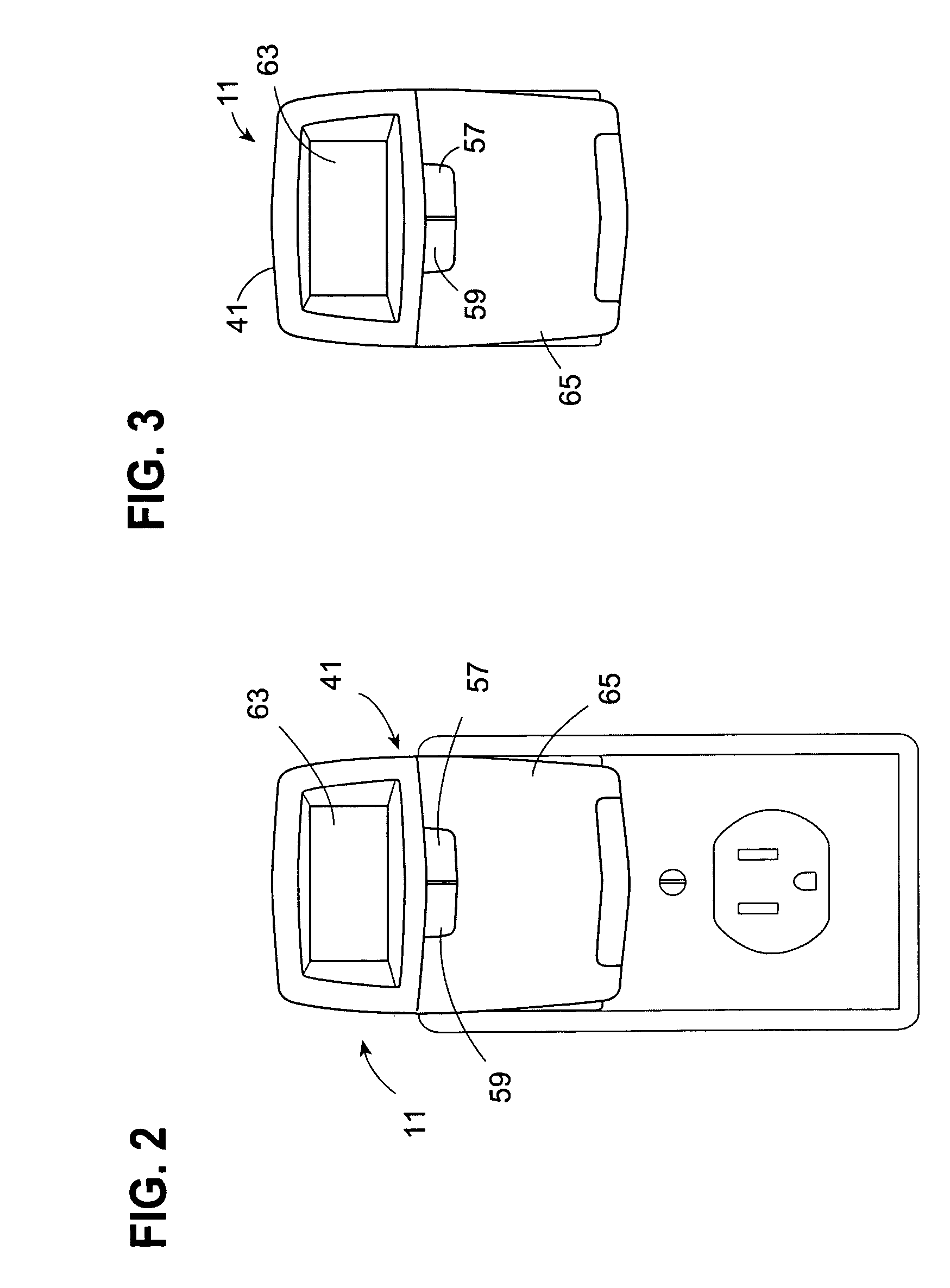
[0024] The present invention generally relates to an electronic timer which is programmed to automatically activate and deactivate electronic devices to which it is coupled, such as lights (both indoor and outdoor), appliances and the like based on sunrise and sunset times of a particular geographic location.

[0025] Over the course of a given year, the sunset and sunrise times will vary from day to day, week to week and month to month. For example, the sunset time in Portland, Me. is approximately 4:09 p.m. on Dec. 24 of each year. As the year progresses, the time of sunset in Portland, Me. occurs later in the day. For example, on Jun. 24 of each year, the sun sets in this city at approximately 7:13 p.m. Similarly, as noted herein, the sunrise and sunset times in their respective time zones for different cities and states throughout the country will vary on any given day. For example, on Dec. 24, the sunset time in Portland, Me. is approximately 4:09 p.m. whereas the sunset time in...


PUM


Abstract

The present invention generally relates to an electrical timer which automatically controls the activation and deactivation of electrical devices, such as light fixtures, appliances and the like based on the time of sunrise and / or sunset for a particular geographic location. In this regard, the sunrise and / or sunset times for a multitude of different geographic locations is collected and stored in the timer's memory in association with the relevant geographic location. Each geographic location is specified in memory by geographic indicia, such as postal zip code or telephone area code, of its location (e.g., latitude and longitude). The timer of the present invention is programmed to automatically activate and / or deactivate the device to which it is coupled (e.g., lights, appliances, etc.) at the sunset and / or sunrise times stored in memory for each date that is specified in memory.

Description

FIELD OF THE INVENTION [0001] The present invention generally relates to an electronic timer which automatically controls the activation and deactivation of devices to which it is coupled, such as light fixtures, appliances and the like, based on the time of sunrise and / or sunset for a particular geographic location. BACKGROUND OF THE INVENTION [0002] Electronic timers for controlling the activation and deactivation of light fixtures are well known in the art. Typically, these timers can be programmed by a user to activate or deactivate household lights at a predetermined time. For example, a conventional electronic wall timer could be programmed to activate external lighting at a residence at a predetermined time which is estimated to be the time at which the sun sets. This can be done manually, however, the disadvantage of having to manually set a timer is that the timer will have to be reset periodically in order to adapt the timer to the change in sunset time. [0003] In some cas...

Claims


Application Information

Patent Timeline
IPC IPC(8): G04F10/00G04F8/00
CPCG04G9/0076G04G15/006H05B37/0281Y02B20/42H05B47/16Y02B20/40
Inventor HUIZI, ANDREW H.HITCHCOCK, MYRONDRISKA, JOHN J.
Owner HARDWARE INNOVATIONS
Learn More