Visiting place identification device and visiting place identification method

Active Publication Date: 2006-07-06
GK BRIDGE 1
View PDF2 Cites 114 Cited by
  • Summary
  • Abstract
  • Description
  • Claims
  • Application Information

AI Technical Summary

Benefits of technology

[0013] Accordingly, the storage unit stores the information of the identified visited place as a history, which enables to learn accurately

Problems solved by technology

For example, when the user visits a shopping mall that packs a plurality of facilities, a multi-tenant building that accommodates a plurality of independent sh

Method used


Image

  • Visiting place identification device and visiting place identification method
  • Visiting place identification device and visiting place identification method
  • Visiting place identification device and visiting place identification method

Examples


first embodiment

[0063] The following describes the first embodiment according to the present invention with reference to the drawings.

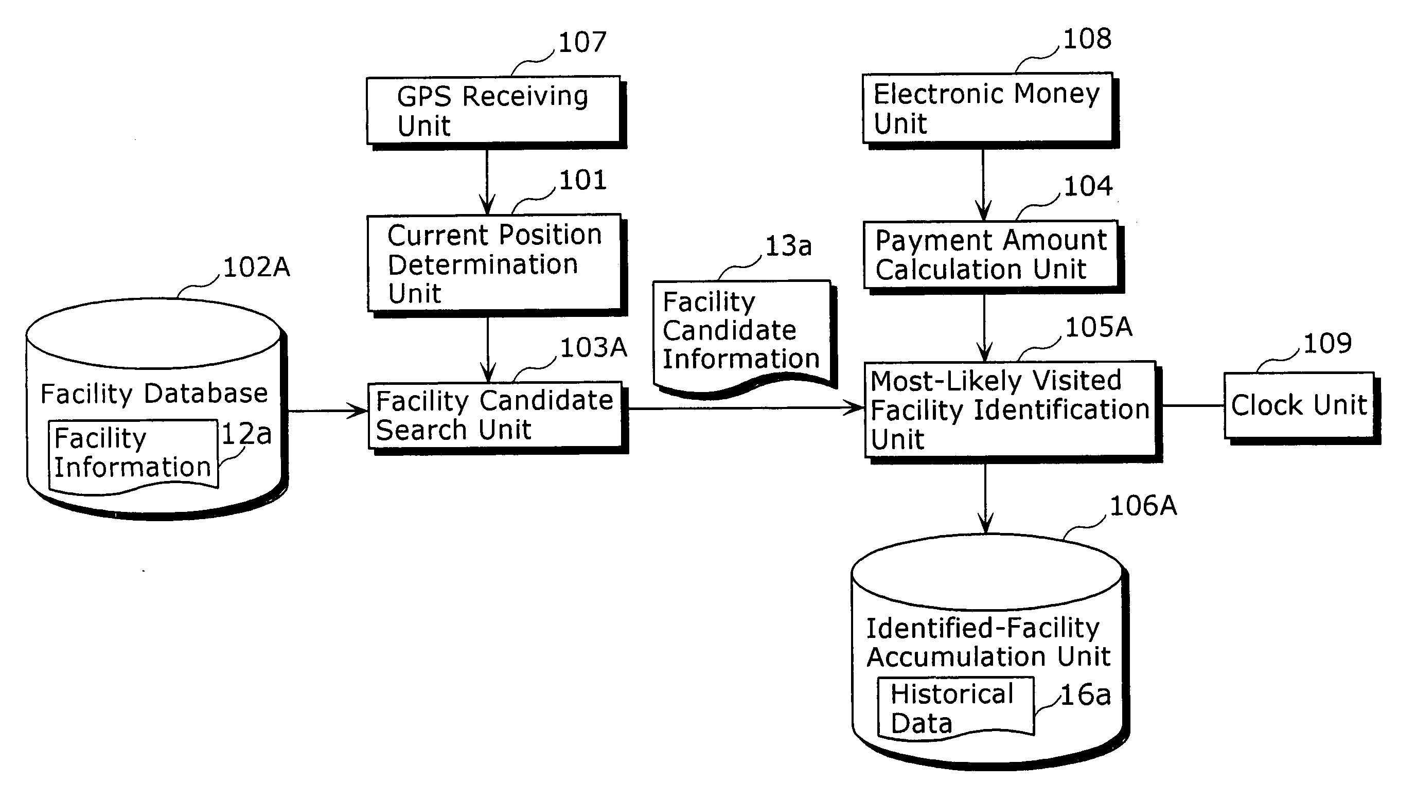
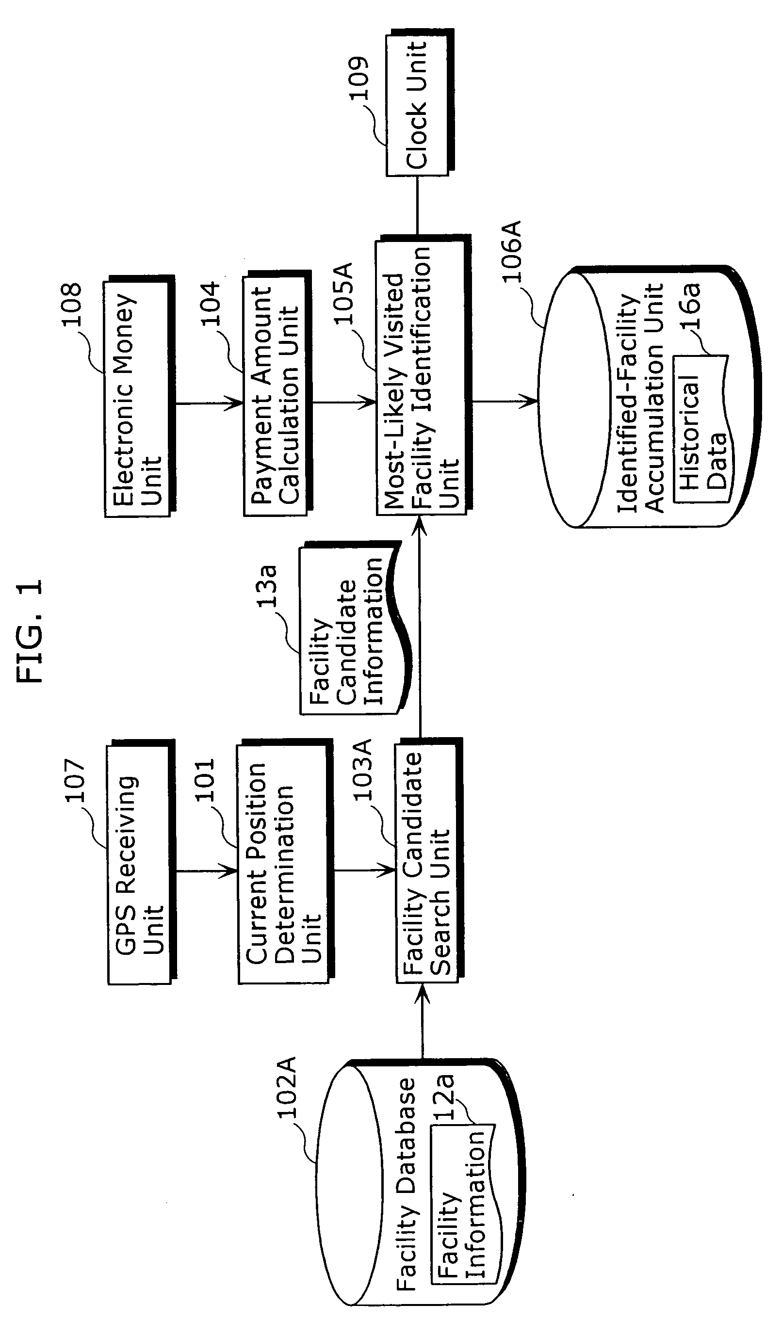
[0064]FIG. 1 is a block diagram that depicts a structure of the visited-place identification apparatus according to the first embodiment of the present invention.

[0065] The visited-place identification apparatus according to the first embodiment identifies a user's visited facility with high accuracy, and then accumulates a history of such identified visited facilities. The visited-place identification apparatus includes a GPS receiving unit 107, a current position determination unit 101, a facility database 102A, a facility candidate search unit 103A, an electronic money unit 108, a payment amount calculation unit 104, a most-likely visited facility identification unit 105A, a clock unit 109 and an identified-facility accumulation unit 106A. Note that the visited-place identification apparatus according to the first embodiment is embedded in portable terminals, su...

second embodiment

[0105] The following describes the second embodiment according to the present invention with reference to the drawings.

[0106]FIG. 6 is a block diagram that depicts a structure of the visited-place identification apparatus according to the second embodiment of the present invention.

[0107] The visited-place identification apparatus according to the second embodiment identifies a user's visited facility with high accuracy, and accumulates a history of such identified visited facilities. The visited-place identification apparatus includes a GPS receiving unit 107, a current position determination unit 101, a facility database 102B, a facility candidate search unit 103B, a stay determination unit 201, a stay time calculation unit 202, a most-likely visited facility identification unit 105B, a clock unit 109 and an identified-facility accumulation unit 106B. Note that the visited-place identification apparatus according to the second embodiment is embedded in portable terminals, such as...

third embodiment

[0145] The following describes the third embodiment according to the present invention with reference to the drawings.

[0146]FIG. 11 is a block diagram that depicts a structure of the visited-place identification apparatus according to the third embodiment of the present invention.

[0147] The visited-place identification apparatus according to the third embodiment identifies a user's visited facility with high accuracy and accumulates a history of such identified visited facilities. The visited-place identification apparatus includes a GPS receiving unit 107, a current position determination unit 101, a facility database 102C, a facility candidate search unit 103C, an electronic money unit 108, a payment amount calculation unit 104, a most-likely visited facility identification unit 105C, a clock unit 109, an identified-facility accumulation unit 106A, a facility category search unit 302, and a facility payment amount storage unit 301. The visited-place identification apparatus acco...


PUM


Abstract

The present invention includes: a current position determination unit (101) that determines a current position of a user; a facility candidate search unit (103A) that specifies, as a candidate for a visited place, a facility that is located within a predetermined area including the current position determined by the current position determination unit (101); an electronic money unit (108) and a payment amount calculation unit (104) that detect a payment amount of the user; and a most-likely visited facility identification unit (105A) that identifies a most-likely visited place by selecting from a plurality of facilities a facility corresponding to the payment amount detected by the electronic money unit (108) and the payment amount calculation unit (104), when the plurality of facilities are specified by the facility candidate search unit (103A).

Description

TECHNICAL FIELD [0001] The present invention relates to an apparatus and a method for identifying a place where a user has visited. BACKGROUND ART [0002] In recent years, various mobile terminals have been utilized. These mobile terminals include a vehicle navigation apparatus that determines a user's position using the Global Positioning System (GPS) and guides the user to a destination, a portable telephone that provides a user with information regarding facilities in the vicinity of a user's current position using a positioning system with a base station, and the like. [0003] Under such circumstances, technologies have been proposed for modeling the user's behavior and travel patterns, using a history of the position information obtained by such mobile terminals (for example, refer to Japanese Laid-Open Patent Application No. 11-149596 publication, FIG. 1). [0004] The above patent document discloses that a vehicle-equipped information apparatus accumulates beforehand time-series ...

Claims


Application Information

Patent Timeline
IPC IPC(8): G06Q99/00G01C21/00G01C21/26G06F17/30G06Q10/00G06Q50/00G06Q50/10G07F7/00G08G1/005G08G1/0969H04W4/02
CPCG06Q20/367G06Q20/4014G06Q30/06G07F17/0014
Inventor MATSUURA, SATOSHIKUDO, TAKAHIROOZAWA, JUNYOSHIOKA, MOTOTAKA
Owner GK BRIDGE 1
Why Eureka
Try Eureka