Debugging apparatus
- Summary
- Abstract
- Description
- Claims
- Application Information
AI Technical Summary
Benefits of technology
Problems solved by technology
Method used
Image
Examples
first embodiment
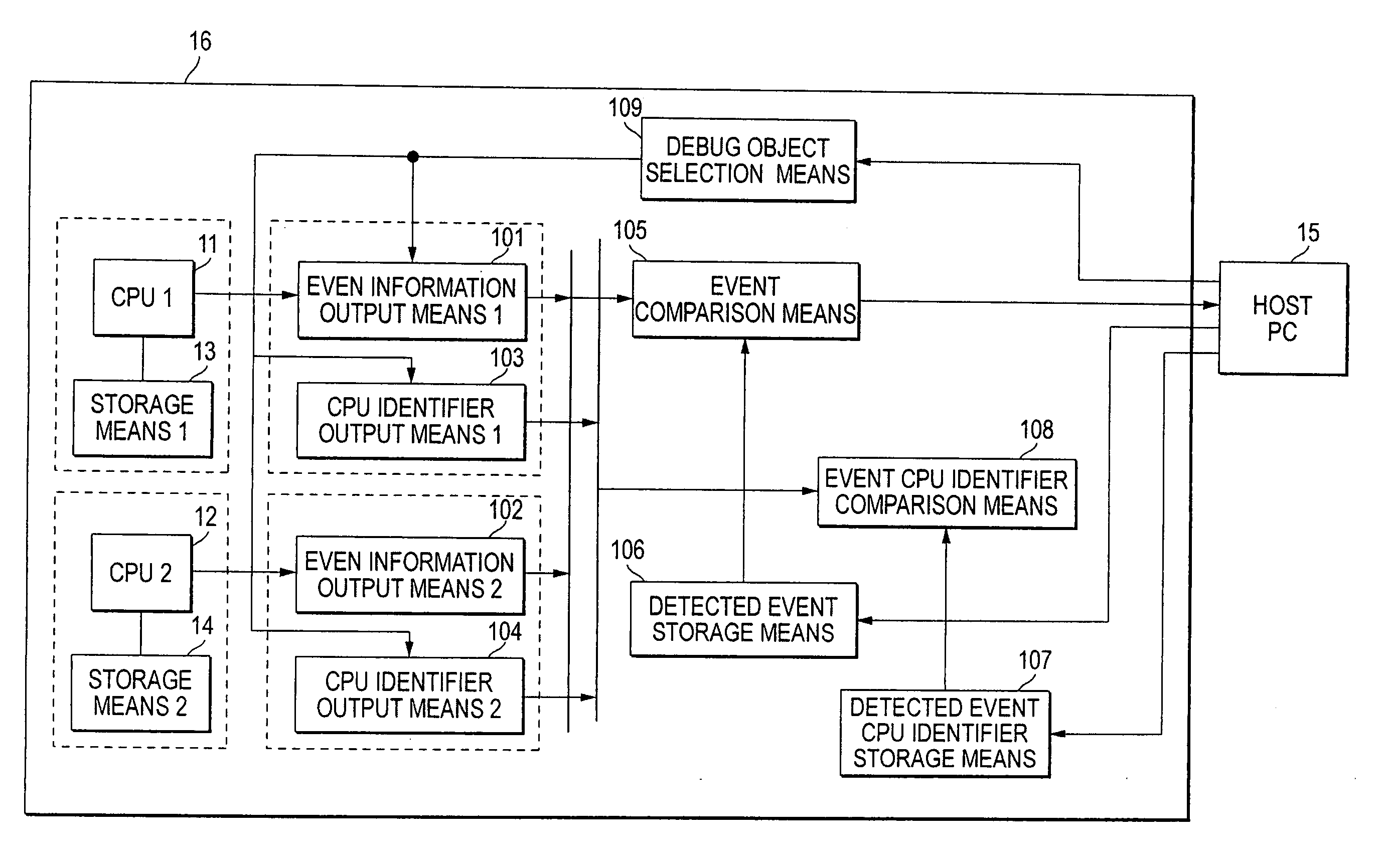
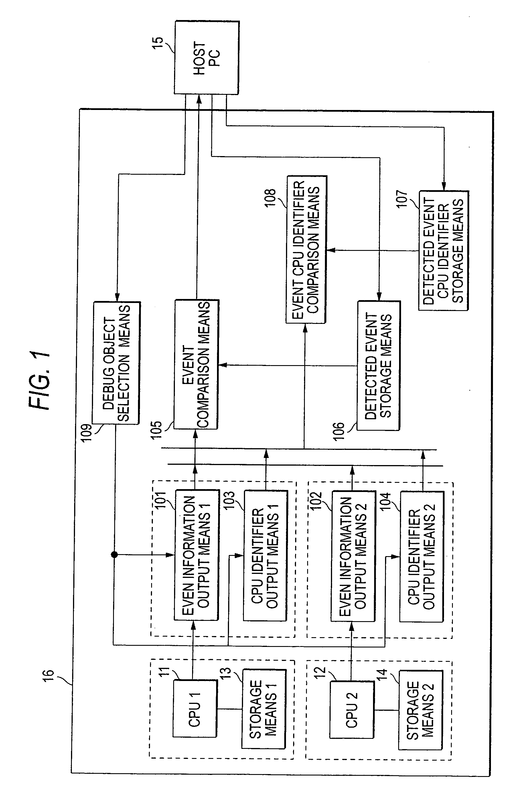
[0048]FIG. 1 is a block diagram of a debugging apparatus according to a first embodiment of the invention. In FIG. 1, a system LSI 116 is made up of a plurality of CPUs 11 and 12, storage means 13 and 14 connected to the CPUs 11 and 12 respectively, event information output means 101 and 102, CPU identifier output means 103 and 104, event comparison means 105, detected event storage means 106, detected event CPU identifier storage means 107, event CPU identifier comparison means 108, and debug object selection means 109, and is connected to a host PC 15 of a host computer.
[0049] Instructions executed by the CPU 11 and data used by the CPU 11 are stored in the storage means 13, and instructions executed by the CPU 12 and data used by the CPU 12 are stored in the storage means 14. The host PC 15 specifies the CPU to be debugged for the debug object selection means 109. Here, as the debug object, only the CPU 11, only the CPU 12, or either of the CPU 11 and the CPU 12 can be selected....
second embodiment
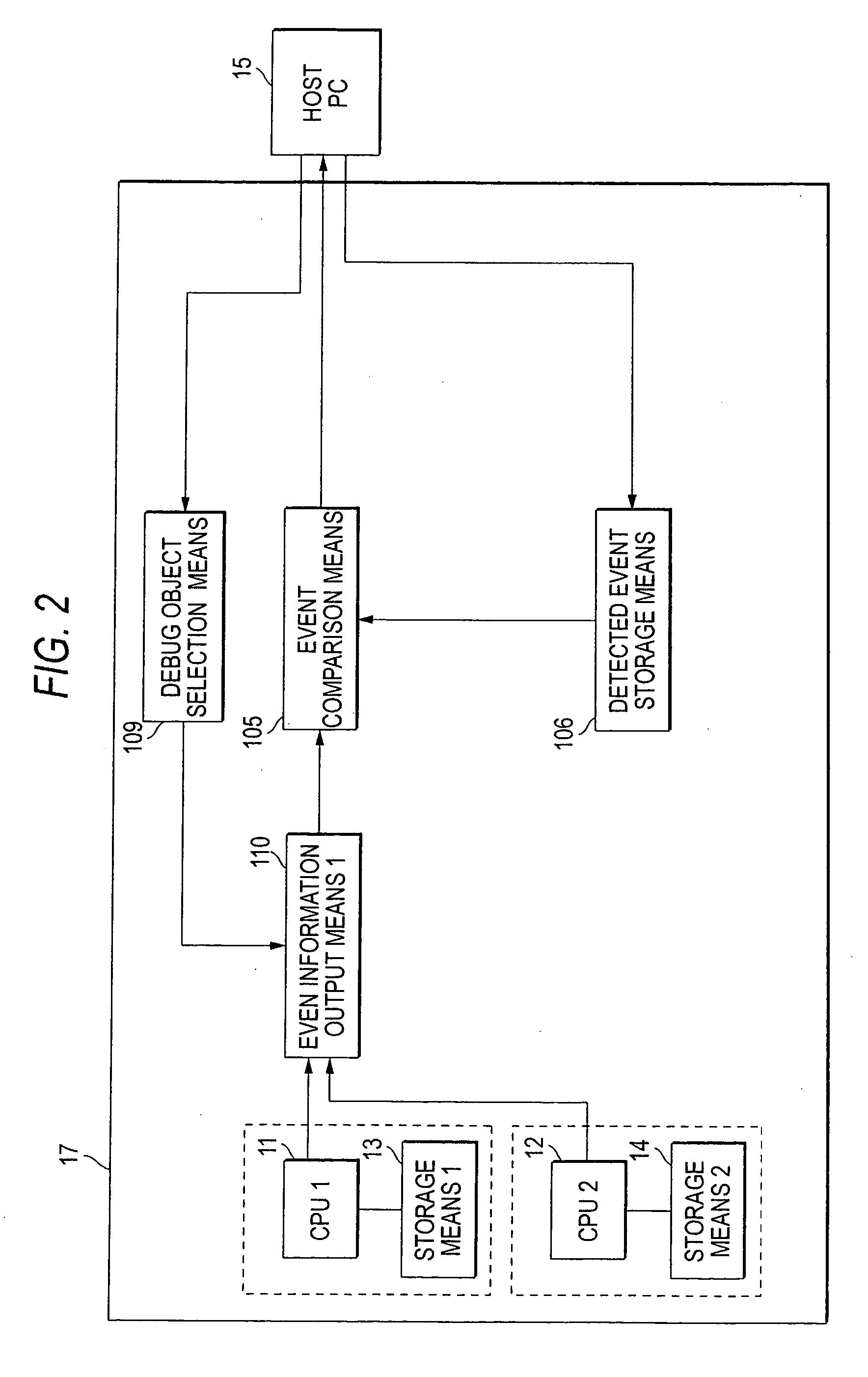
[0057]FIG. 2 is a block diagram of a debugging apparatus according to a second embodiment of the invention. In FIG. 2, a system LSI 117 is made up of a plurality of CPUs 11 and 12, storage means 13 and 14 connected to the CPUs 11 and 12 respectively, event information output means 110, debug object selection means 109, event comparison means 105, and detected event storage means 106, and is connected to a host PC 15.
[0058] The host PC 15 specifies the CPU to be debugged for the debug object selection means 109. The debug object is only the CPU 11 or only the CPU 12 and a plurality of CPUs cannot be selected at the same time. The debug object selection means 109 notifies the event information output means 110 of the CPU to be debugged.
[0059] If the debug object is the CPU 11, the event information output means 110 outputs the internal operation event of the CPU 11 to the event comparison means 105; if the debug object is the CPU 12, the event information output means 110 outputs th...
third embodiment
[0063]FIG. 3 is a block diagram of a debugging apparatus according to a third embodiment of the invention. In FIG. 3, a system LSI 118 is made up of a plurality of CPUs 11 and 12, storage means 13 and 14 connected to the CPUs 11 and 12 respectively, event information output means 110, detected event group storage means 111, a detected event counter 113, debug object selection means 109, detected event storage means 106, event comparison means 105, detected event transfer means 112, and event storage switching means 114, and is connected to a host PC 15.
[0064] The host PC 15 notifies the debug object selection means 109 of the CPU to be debugged. As the debug object, only the CPU 11 or only the CPU 12 can be selected. At the same time, exclusive debugging can be selected. To select the CPU 11 as the debug object and debug the CPU 11 exclusively, the CPU 12 is stopped; to select the CPU 12 as the debug object and debug the CPU 11 exclusively, the CPU 11 is stopped.
[0065] If the CPU ...
PUM
 Abstract
Description
Claims
Application Information
 - R&D
- Intellectual Property
- Life Sciences
- Materials
- Tech Scout
- Unparalleled Data Quality
- Higher Quality Content
- 60% Fewer Hallucinations
Browse by: Latest US Patents, China's latest patents, Technical Efficacy Thesaurus, Application Domain, Technology Topic, Popular Technical Reports.
© 2025 PatSnap. All rights reserved.Legal|Privacy policy|Modern Slavery Act Transparency Statement|Sitemap|About US| Contact US: help@patsnap.com


