
One-position fill-up and circulating tool

Inactive Publication Date: 2006-07-13
WEATHERFORD TECH HLDG LLC
View PDF99 Cites 46 Cited by
  • Summary
  • Abstract
  • Description
  • Claims
  • Application Information

AI Technical Summary

Benefits of technology

[0015] In another embodiment, an apparatus for handling a tubular comprises a gripping apparatus and a fluid conduit coupled to the gripping apparatus. The fluid conduit comprises a body insertable into the tubular, the body having a bore thereof; and a sealing element disposed around the body, the sealing element moveable between a first position and a second position relative to the tubular without moving the body relative to the tubular, wherein after insertion into the tubular, the sealing element, in the first position, substantially prevents fluid flow past the sealing element is at least substantially prevented, and, in the second position, allows fluid flow past the sealing element. In another embodiment, the gripping apparatus is adapted to engage an interior surface of the tubular. In yet another embodiment, the gripping apparatus is adapted to engage an exterior surface of the tubular.

Problems solved by technology

Rigging up and rigging down the circulating tool, which are time-consuming procedures, must often be performed numerous times during a casing running operation.
Therefore, attaching and re-attaching the circulating tool each time the casing is stuck within the wellbore during casing running is expensive and decreases the profitability of the well.
Furthermore, because rig personnel perform the rigging up and rigging down of the circulating tool, which are often dangerous operations, numerous rigging up and rigging down operations decrease the safety of the well site.

Method used


Image

  • One-position fill-up and circulating tool
  • One-position fill-up and circulating tool
  • One-position fill-up and circulating tool

Examples


Embodiment Construction

[0022] Embodiments of the present invention advantageously provide a one-position fill-up and circulating tool for running casing into a wellbore. The fill-up / circulating tool of embodiments of the present invention eliminates the dangerous and costly procedure of repeatedly inserting and removing the prior art circulating tool from the casing while running the casing into the wellbore.

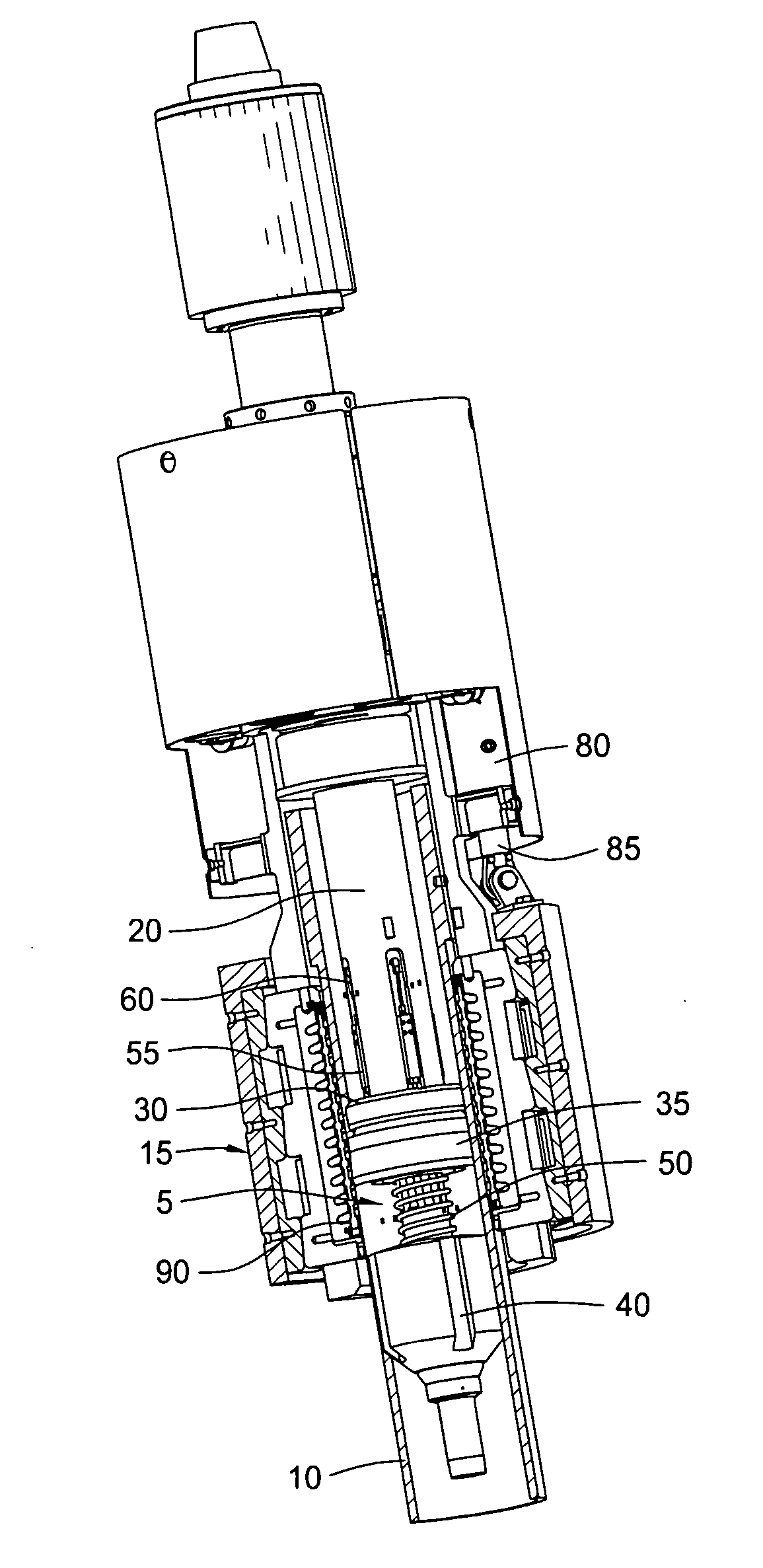
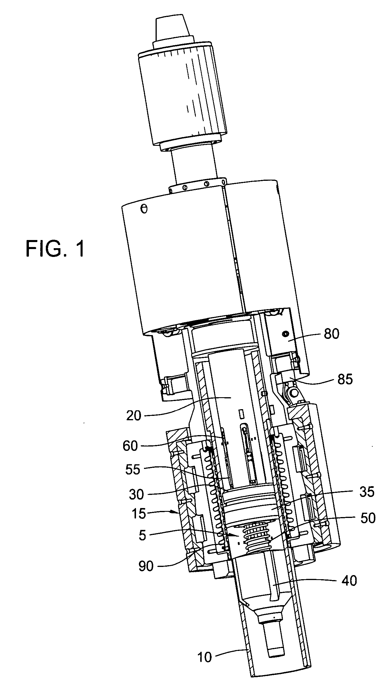
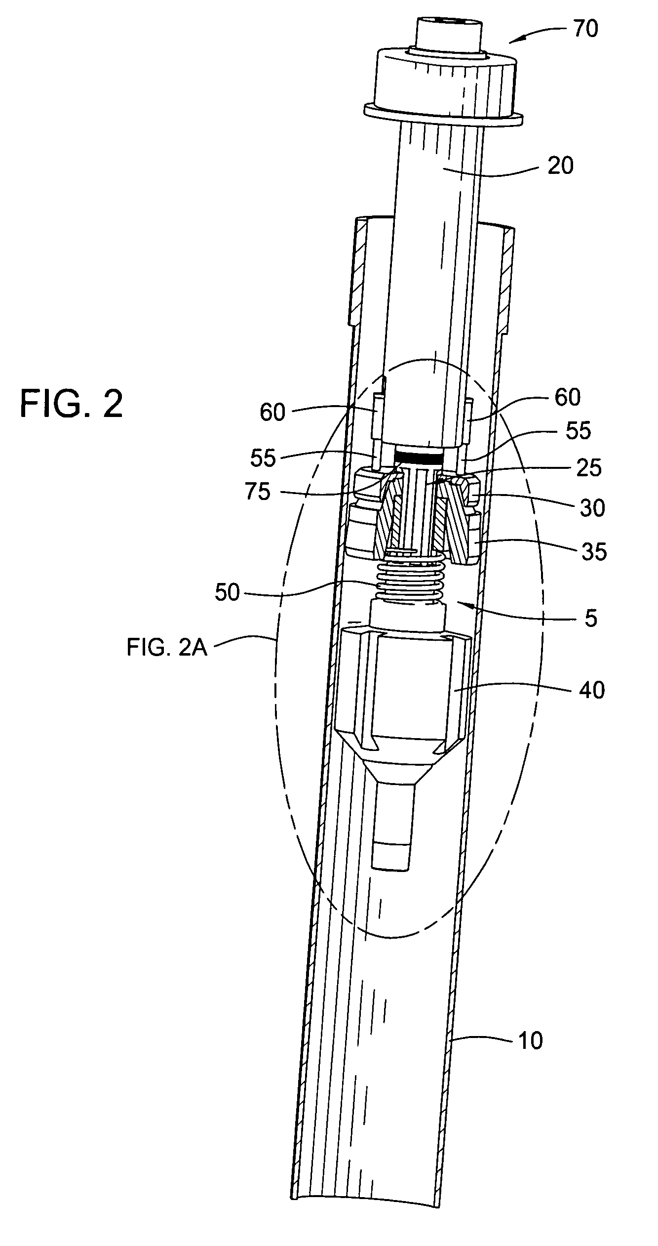
[0023]FIG. 1 illustrates a fill-up / circulating tool 5 inserted into an upper portion of casing 10. A lower portion of the fill-up / circulating tool 5 is disposed within a bore of the casing 10, while an upper end of the fill-up / circulating tool 5 is attached by a connecting member 70 (see FIGS. 2 and 3) to a gripping head such as a torque head 15 capable of grippingly engaging the outer diameter of the casing 10. The connecting member 70 may include threads on its upper end for mating with corresponding threads within the torque head 15, or the connecting member 70 may be provided in the form of any o...


PUM


Abstract

Embodiments of the present invention include methods and apparatus for circulating fluid through casing and filling the casing with fluid using a combination fill-up and circulating tool while maintaining the fill-up / circulating tool in substantially the same position relative to the casing. In one embodiment, the fill-up / circulating tool includes a mandrel insertable into casing and having a sealing element therearound, the sealing element capable of sealingly engaging with an outer diameter of the mandrel to permit circulating fluid through the casing. The fill-up / circulating tool is also capable of allowing air flow around the outer diameter of the mandrel for the operation of filling the casing with fluid without the need to move the mandrel within the casing.

Description

CROSS-REFERENCE TO RELATED APPLICATIONS [0001] This application claims benefit of co-pending U.S. Provisional Patent Application Ser. No. 60 / 643,339, filed on Jan. 12, 2005, which application is herein incorporated by reference in its entirety.BACKGROUND OF THE INVENTION [0002] 1. Field of the Invention [0003] Embodiments of the present invention generally relate to running a tubular into a wellbore. More specifically, embodiments of the present invention relate to using a circulating tool for running casing into a wellbore. [0004] 2. Description of the Related Art [0005] To obtain hydrocarbons from an earth formation, a wellbore is typically drilled to a first depth using a drill string having a drill bit attached to its lower end. The drill string is then removed, and thereafter a first casing is lowered into the wellbore to line the wellbore. The casing may be a casing section or, in the alternative, a casing string including two or more casing sections threadedly connected to on...

Claims


Application Information

Patent Timeline
IPC IPC(8): E21B19/00
CPCE21B21/00E21B21/10E21B33/126E21B21/106E21B33/04E21B33/05
Inventor SHAHIN, DAVID
Owner WEATHERFORD TECH HLDG LLC
Learn More