Nagative brake device, construction machine, and method of activating negative

Inactive Publication Date: 2006-07-13
HITACHI SUMITOMO HEAVY IND CONSTR CRANE CO LTD
View PDF3 Cites 15 Cited by
  • Summary
  • Abstract
  • Description
  • Claims
  • Application Information

AI Technical Summary

Benefits of technology

[0009] In this manner, by means of a general purpose pressure-reducing valve, th

Problems solved by technology

With the device in the aforementioned publication, because oil chambers are provided on both sides of the brake piston and oil flows to each oil chamber are to be controlled, the structure of the brake appar

Method used


Image

  • Nagative brake device, construction machine, and method of activating negative
  • Nagative brake device, construction machine, and method of activating negative
  • Nagative brake device, construction machine, and method of activating negative

Examples


modified examples

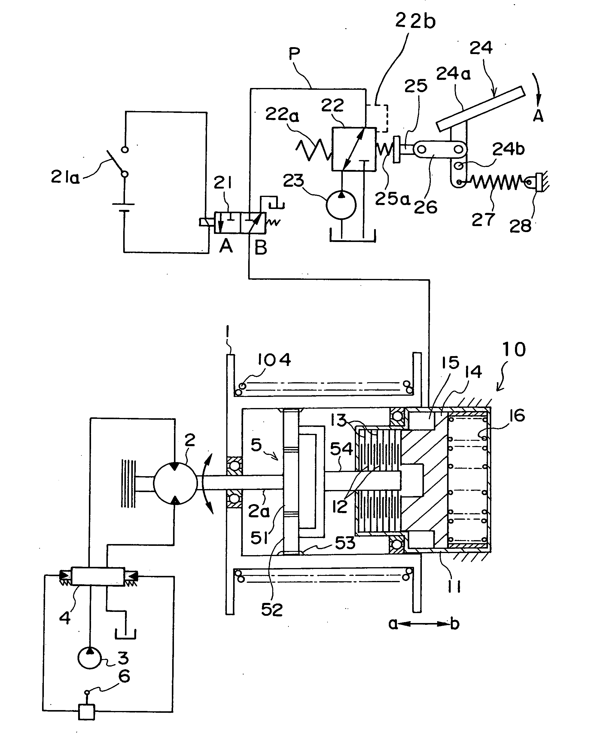
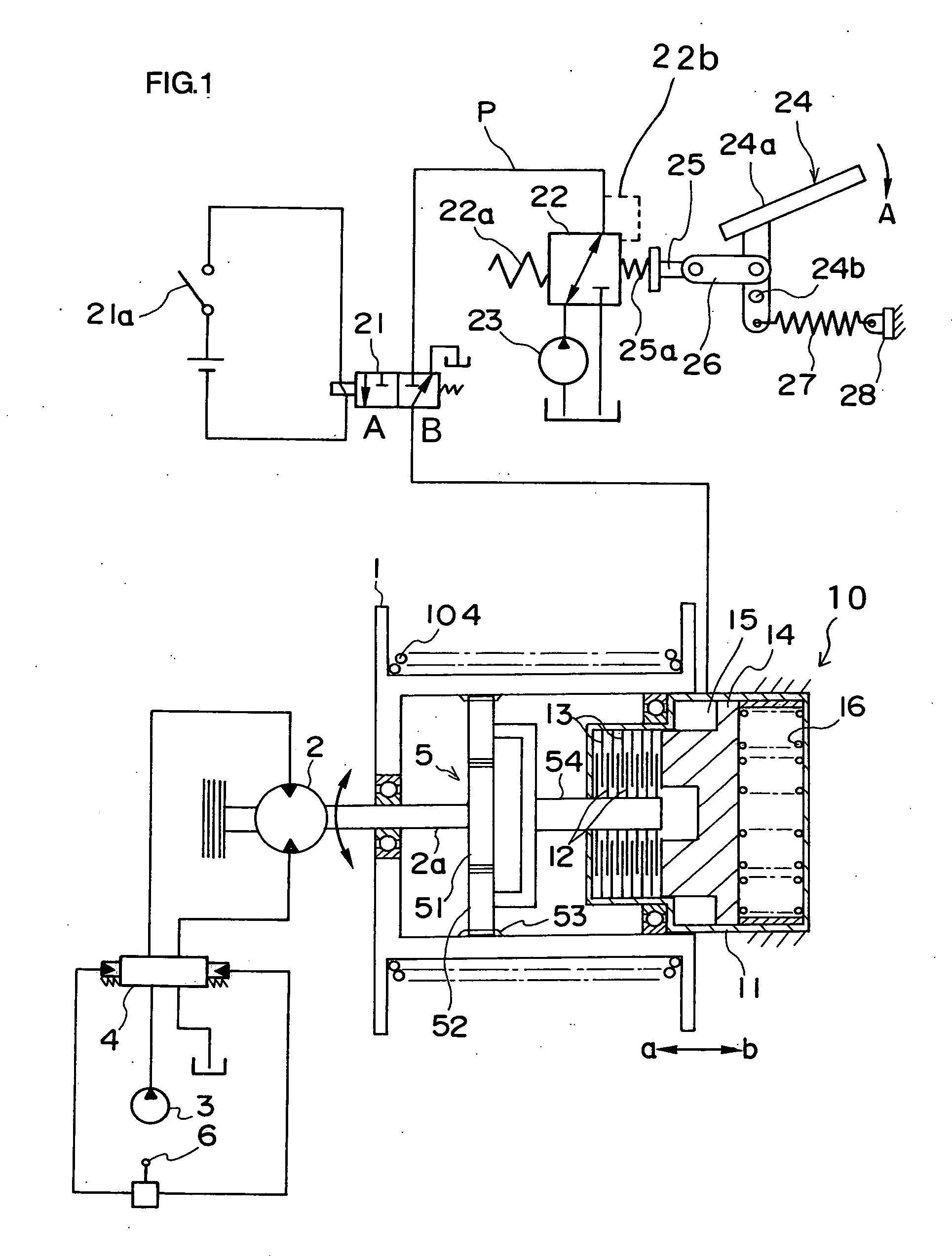
[0046] When the urging force of the spring 16 acting on the brake piston 14 is taken to be B1, the hydraulic pressure of the oil chamber 15 resisting this urging force is taken to be B2, and the brake force acting on the drum 1 is taken to be B, the relationship between B1, B2 and B and the extent of operation of the pedal is, for example, shown in FIG. 9. Namely, the urging force B1 is fixed regardless of the extent of operation of the pedal, while the hydraulic pressure B2 changes in accordance with the characteristic (the characteristic of FIG. 3(b)) of the pressure-reducing valve 22.

[0047] Here, when the initial length of the spring 16 is set offset from an appropriate value due to the parts manufacturing tolerance and assembly error, etc., the spring characteristic is shifted, for example, from the characteristic B1 (solid line) of FIG. 9 to the characteristic B1a (dotted line). As a result, the brake force characteristic shifts from B (solid line) to Ba (dotted line). As a re...


PUM


Abstract

The present invention includes a hydraulic source (23), a pressure reducing valve (22) that reduces hydraulic pressure from the hydraulic source (23) so as secondary pressure P to become large in accordance with increase in an extent to which a pusher (25) is pressed in, a negative brake mechanism (10) that releases braking by secondary pressure P from the pressure-reducing valve (22) and causes braking to operate in response to cutting of secondary pressure (P), a brake pedal (24) provided so as to pull out the pusher (25) according to a depression operation, and a spring member (27) that pushes in the pusher (25) so as to release braking performed by the negative brake mechanism (10) when the brake pedal (24) is not operated.

Description

TECHNICAL FIELD [0001] The present invention relates to negative brake apparatus for releasing a brake using hydraulic pressure and operating a brake by interrupting the hydraulic pressure, construction machinery, and a negative brake method. BACKGROUND ART [0002] Cranes equipped with this type of negative brake apparatus are known in the related art (for example, Japanese Laid Open Patent Publication No. H9-216793). According to this publication, oil chambers are provided on both sides of a brake piston, with negative braking being released upon supplying pressurized oil to one of the oil chambers, and a hydraulic brake being operated upon supplying pressurized oil to the other oil chamber according to operation of a brake pedal. When the supply of oil to an oil chamber for brake release use is cut, negative braking acts due to the urging force of a spring. [0003] With the device in the aforementioned publication, because oil chambers are provided on both sides of the brake piston ...

Claims


Application Information

Patent Timeline
IPC IPC(8): F16D55/36B66D1/44B66D5/26F16D55/40
CPCB66D5/26
Inventor HONJOU, KOUHEIDATE, KENICHIROUHOSHINO, HIROYUKI
Owner HITACHI SUMITOMO HEAVY IND CONSTR CRANE CO LTD
Why Eureka
Try Eureka