Metal to plastic fluid connection with overmolded anti-rotation retainer

a technology of plastic fluid and metal to plastic, which is applied in the direction of hose connection, branching pipe, mechanical apparatus, etc., can solve the problems of relatively heavy braze block, high cost of brazing, and relatively difficult control

Active Publication Date: 2006-07-13
COOPER STANDARD AUTOMATIVE INC
View PDF31 Cites 54 Cited by
  • Summary
  • Abstract
  • Description
  • Claims
  • Application Information

AI Technical Summary

Benefits of technology

[0004] A fluid connection assembly includes a metal tube having a flared end and a plastic manifold having a port. The port includes an annular collar and an annular recess that receives a seal. The metal tube is arranged over the port and engages the seal. When the metal tube is arranged over the port, the flared end abuts the annular collar of the port. Once the metal tube is installed on the port of the manifold, a plastic retainer is molded over the annular collar of the port and the flared end of the metal tube to retain the metal tube axially on the port of the manifold. The material of the retainer enters a locating feature on the port and the metal tube to prevent rotation of the metal tube relative to the manifold.
[0005] Alternately, the port includes a flared end and the metal tube includes an annular collar. The metal tube is inserted into the port, and the annular collar of the metal tube engages the flared end of the port to prevent over insertion of the metal tube into the port. A seal is received in a recess in the metal tube. When the metal tube is inserted into the port, the seal is located between the metal tube and the port. A retainer is molded over the annular collar of the metal tube and the flared end of the port to retain the metal tube axially on the port of the manifold.

Problems solved by technology

However, there are several drawbacks to brazing.
For one, brazing is expensive and relatively difficult to control.
Additionally, if a non-uniform braze bead is formed, leaks may occur between the metal tube and the fluid housing.
Moreover, the braze block is relatively heavy.

Method used


Image

  • Metal to plastic fluid connection with overmolded anti-rotation retainer
  • Metal to plastic fluid connection with overmolded anti-rotation retainer
  • Metal to plastic fluid connection with overmolded anti-rotation retainer

Examples


third embodiment

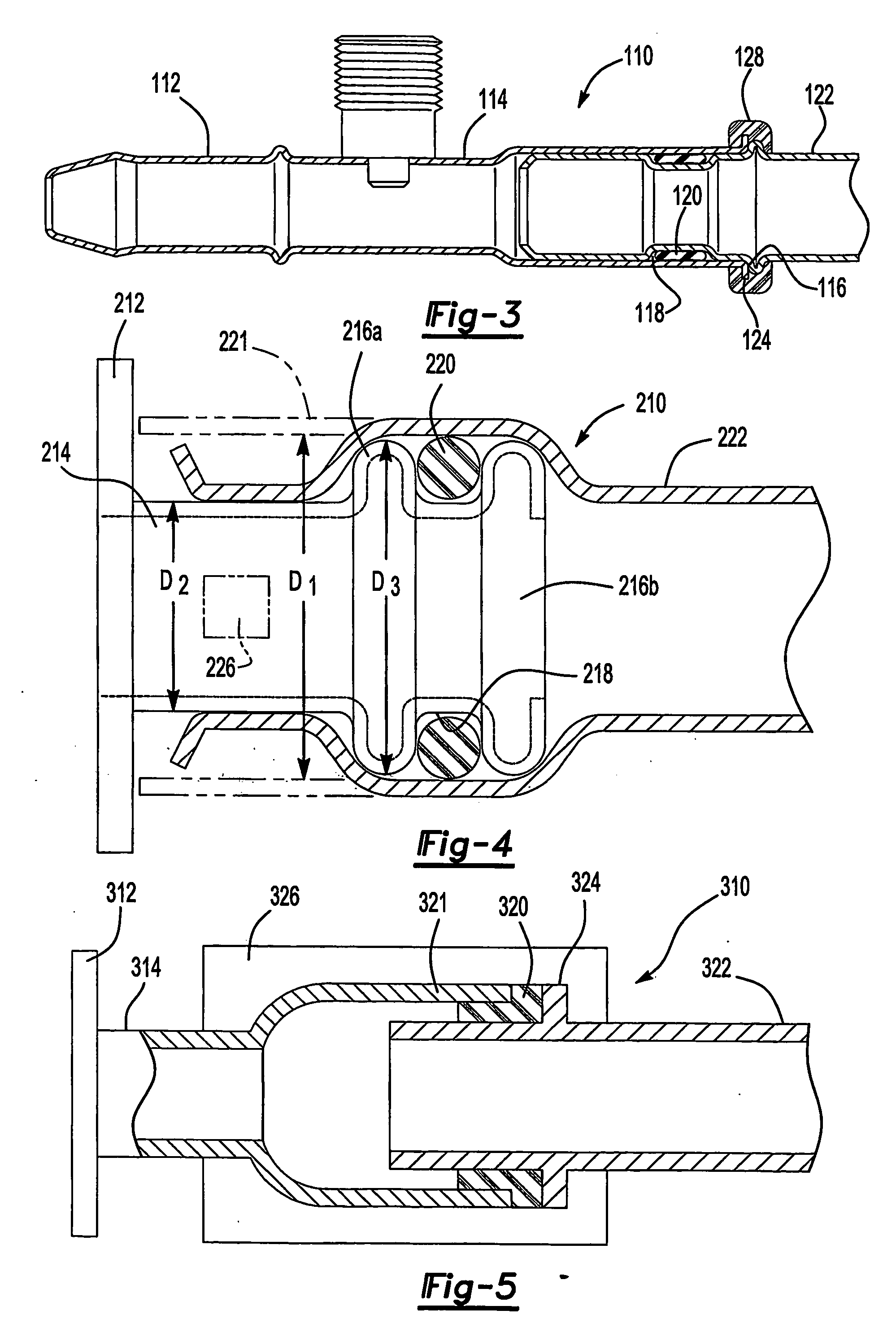
[0021]FIG. 4 illustrates a fluid connection assembly 210 including a manifold 212 having port 214. The port 214 includes two annular collars 216a and 216b and an annular recess 218 located between the two annular collars 216a and 216b. Each of the two annular collars 216a and 216b has an outer diameter D3. The annular recess 218 receives a seal 220. In one example, the seal 220 is a rubber O-ring. A metal tube 222 is arranged over the port 214 and engages the seal 220. The port 214 and / or the metal tube 222 can also include a locating feature 226 that positions the metal tube 222 relative to the port 114 of the manifold 212.

[0022] When the metal tube 222 is installed, the end 221 of the metal tube 222 is arranged over the port 214, as shown by the dotted line. The end 221 has an inner diameter D1. The inner diameter D1 of the end 221 of the metal tube 222 is slightly greater than the outer diameter D3 of the two annular collars 216a and 216b. The end 221 of the metal tube 222 is the...

fourth embodiment

[0023]FIG. 5 illustrates a fluid connection assembly 310 including a manifold 312 having port 314. The port 314 includes a flared end 321. A metal tube 322 is inserted into the port 314, compressing a seal 320 between the flared end 321 of the port 314 and the metal tube 322. A retainer 326 is over-molded over the joint of the port 314 of the manifold 312 and the metal tube 322. The retainer 326 compresses the seal 320 and retains the components together. Alternately, the metal tube 322 includes the flared end and the port 314 is inserted into the metal tube 322.


PUM

PropertyMeasurementUnit
inner diameteraaaaaaaaaa
diameteraaaaaaaaaa
moldingaaaaaaaaaa

Abstract

A fluid connection assembly (10) includes a metal tube (22) having a flared end and a plastic manifold (12) having a port (14). The port (14) includes an annular collar (16) and an annular recess (18) that receives a seal (20). The metal tube (22) is arranged over the port (14) and engages the seal (20). The flared end of the metal tube (22) abuts the annular collar (16) of the port (14) when the metal tube (22) is installed. A plastic retainer (28) is molded over the annular collar (16) of the port (14) and the flared end of the metal tube (22) to retain the metal tube (22) axially on the port (14) of the manifold (12). Alternately, the end (221) of the metal tube (222) is crimped to secure the metal tube (222) to the port (214) of the manifold (212).

Description

BACKGROUND OF THE INVENTION [0001] The present invention relates generally to a fluid connection assembly including a metal tube and a plastic housing secured together by a retainer and a method of making the fluid connection assembly. [0002] Numerous fluid connections are used in the art. One type of fluid connection secures a metal tube to a fluid housing. In some applications, the fluid housing is a metal block referred to as a braze block. The metal tube is secured to the fluid housing by brazing. It is advantageous to secure the metal tube to the fluid housing so that the metal tube is in the desired position relative to the fluid housing during shipping and installation. However, there are several drawbacks to brazing. For one, brazing is expensive and relatively difficult to control. Additionally, if a non-uniform braze bead is formed, leaks may occur between the metal tube and the fluid housing. Moreover, the braze block is relatively heavy. [0003] Therefore, there is a need...

Claims


Application Information

Patent Timeline
Patent Type & Authority Applications(United States)
IPC IPC(8): F16L23/00F16L13/00F16L47/00
CPCF16L13/00F16L13/143F16L13/163F16L23/00F16L41/03F16L47/00F16L47/24
Inventor SLUNICK, STEVEN THOMASKANE, NORMAN F.
Owner COOPER STANDARD AUTOMATIVE INC
Why Eureka
Try Eureka