Protection method in a vehicle brake system having electric brakes

a technology of electric brakes and protection methods, which is applied in the direction of brake cylinders, aircraft braking arrangements, anti-theft devices, etc., can solve the problems that the electric motor of the actuator then runs the risk of dangerous overheating, and achieve the effect of reducing the risk of electric motor overheating

Inactive Publication Date: 2006-07-13
SAFRAN LANDING SYSTEMS
View PDF13 Cites 26 Cited by
  • Summary
  • Abstract
  • Description
  • Claims
  • Application Information

AI Technical Summary

Benefits of technology

[0009] An object of the invention is to provide a method of protecting the electric mo...

Problems solved by technology

The electric motors of the actuators t...

Method used


Image

  • Protection method in a vehicle brake system having electric brakes
  • Protection method in a vehicle brake system having electric brakes
  • Protection method in a vehicle brake system having electric brakes

Examples


Embodiment Construction

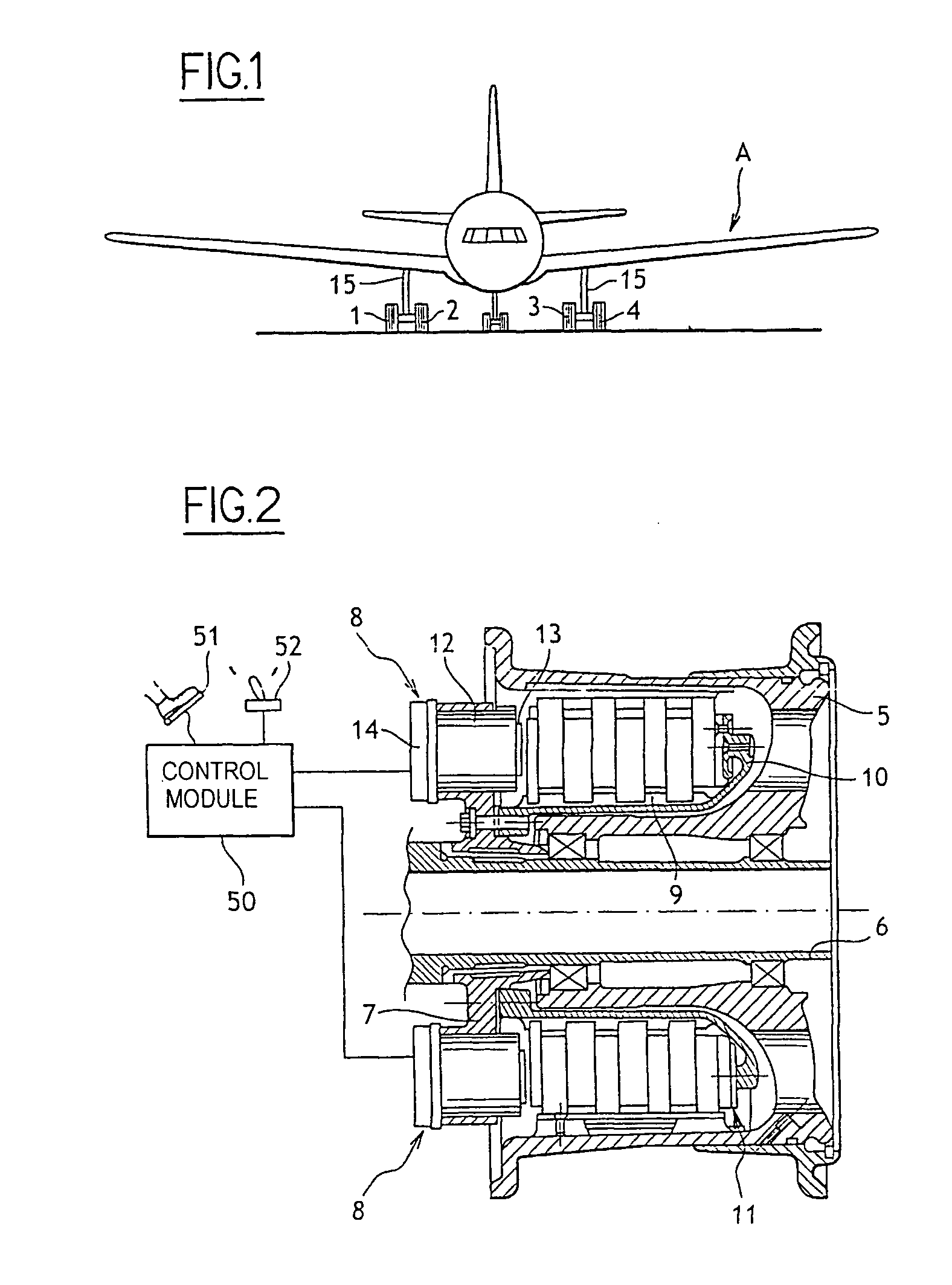
[0023] The method of the invention is described in detail below as used in an aircraft A such as the aircraft shown in FIG. 1 which has four braked wheels numbered 1 to 4, carried by undercarriages 15.

[0024] As shown in FIG. 2, each of the wheels comprises a rim 5 adapted to receive a tire (not shown) and mounted to rotate on an axle 6 carried by one of the undercarriages 15 of the aircraft. A ring 7 carrying electromechanical actuators 8 is mounted on the axle 6.

[0025] A torsion tube 9 that extends inside the rim 5 and that is terminated by an abutment 10 is fastened to the ring 7. The ring 7, and thus the torsion tube 9, are held in rotation relative to the axle 6 by stop means (not shown).

[0026] A stack of disks 11 made up of rotors that are constrained in rotation with the rim 5, and of stators that are constrained in rotation with the torsion tube 9 extends between the abutment 10 and the actuators 8.

[0027] Each of the actuators 8 comprises a body 12 in which a pusher 13 is...


PUM


Abstract

The invention relates to a protection method for protecting from overheating in a vehicle brake system comprising at least one brake provided with at least one electromechanical actuator which comprises a pusher actuated by an electric motor to apply a force selectively onto friction elements of the brake, it being possible for the brake system to operate, at the request of the pilot of the vehicle, either in a controlled mode in which the pusher of the actuator is actuated by the electric motor so as to apply a braking force selectively to the friction elements in response to a braking instruction, or in a parking mode in which the pusher of the actuator is locked in a position in which it exerts a parking force on the friction elements. According to the invention, the method includes the step of acting, while the vehicle is at a standstill, while the brake system is in the controlled mode, and while the pusher is controlled to apply a force on the friction element, to switch automatically and without intervention from the pilot from the controlled mode to the parking mode.

Description

[0001] The invention relates to a protection method in a vehicle brake system having electric brakes. BACKGROUND OF THE INVENTION [0002] Aircraft brake systems are known that comprise brakes provided with electromechanical actuators, each of which comprises a pusher actuated by an electric motor to apply a force selectively onto friction elements of the brake. [0003] Such a brake system can be placed in a controlled mode in which the pushers of the actuators are actuated by the associated electric motors to apply a braking force on the friction elements in response to a braking instruction, which braking instruction is determined as a function of signals coming from the pedals actuated by the pilot, or else as a function of a programmed deceleration. [0004] The brake system can also be placed in a parking mode in which the pushers of the actuators are locked in a position in which they exert a parking force on the friction elements. The parking force is thus maintained in the absenc...

Claims


Application Information

Patent Timeline
IPC IPC(8): B60T17/16F16D65/00
CPCB60T7/12B60T8/00B60T13/741B60T17/221B64C25/44F16D2121/24
Inventor CHICO, PHILIPPEGIROD, PIERRE
Owner SAFRAN LANDING SYSTEMS
Why Eureka
Try Eureka