Eureka AIR delivers breakthrough ideas for toughest innovation challenges, trusted by R&D personnel around the world.

Transmission-controlling device

Inactive Publication Date: 2006-07-13
REXON IND CORP LTD
View PDF6 Cites 9 Cited by
  • Summary
  • Abstract
  • Description
  • Claims
  • Application Information

AI Technical Summary

Benefits of technology

[0006] The primary objective of the present invention is to provide a transmission-controlling device for driving a motor to improve the drawback of the prior art. The transmission-controlling device is to adjust the rotational speed of a motor applied to a power tool to rotate a cutting blade mounted to the power tool to process a workpiece. The transmission-controlling device further provides the user with operational convenience of facilitating the switchover between two kinds of circuit systems for simple switchover of the rotational speed of the motor.
[0007] The foregoing objective of the present invention is attained by the transmission-controlling device, which is composed of a first circuit system, a second circuit system, and a selective switch. The first circuit system is to provide a first voltage. The second circuit system is to provide a second voltage. The selective switch responds to a user's operation to select the first or second voltage to drive the motor so as to change the rotational speed of the motor. Thus, the present invention simplifies and facilitates the switchover of the rotational speed of the motor by employing the selective switch to select the driving voltage for the motor.

Problems solved by technology

For example, a woodworking machine requires only two or three different velocities for the change of the rotational speed, such that conventional transmission-controlling devices are too complicated for such woodworking machine and increase the cost.

Method used


Image

  • Transmission-controlling device
  • Transmission-controlling device
  • Transmission-controlling device

Examples


Embodiment Construction

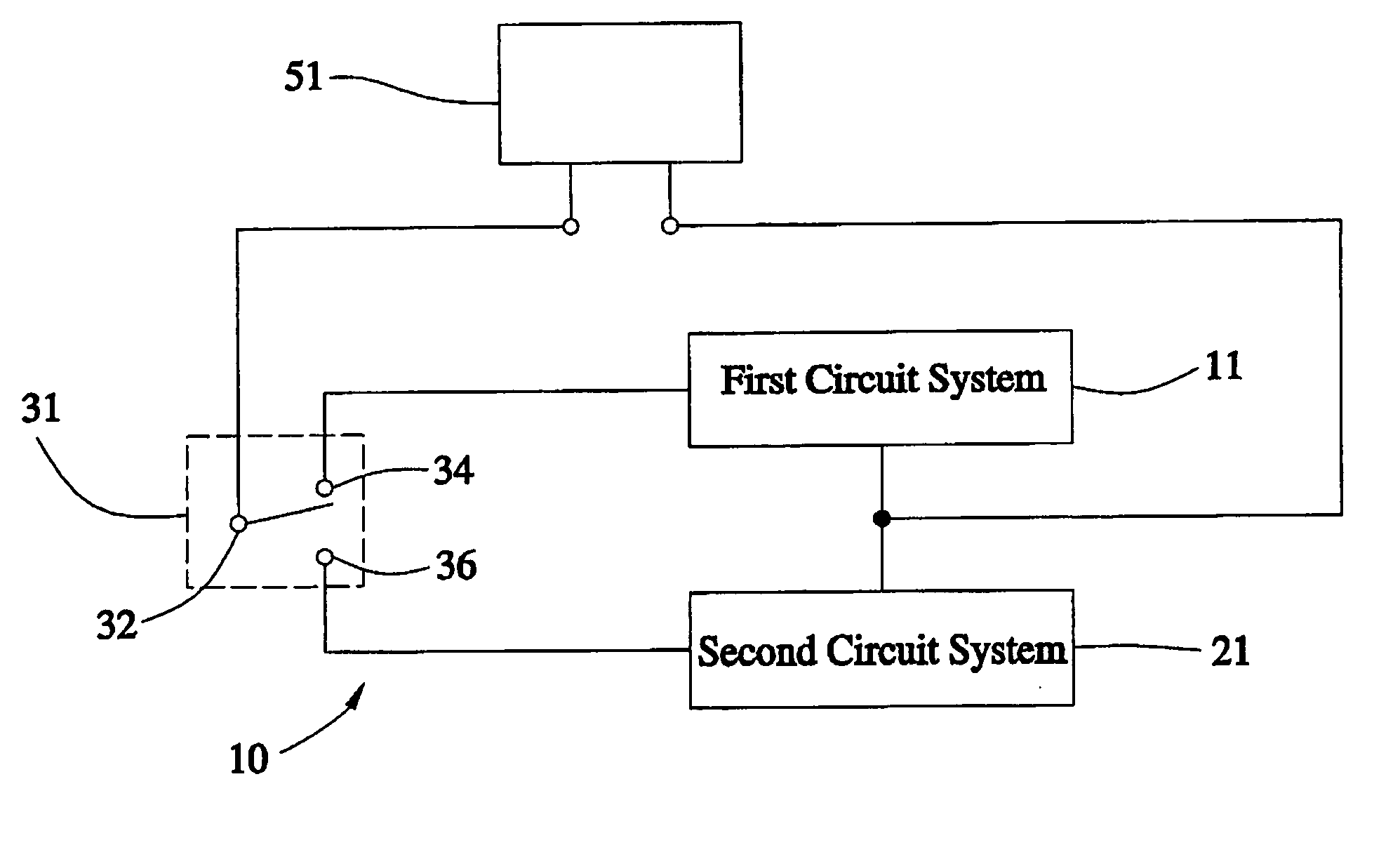
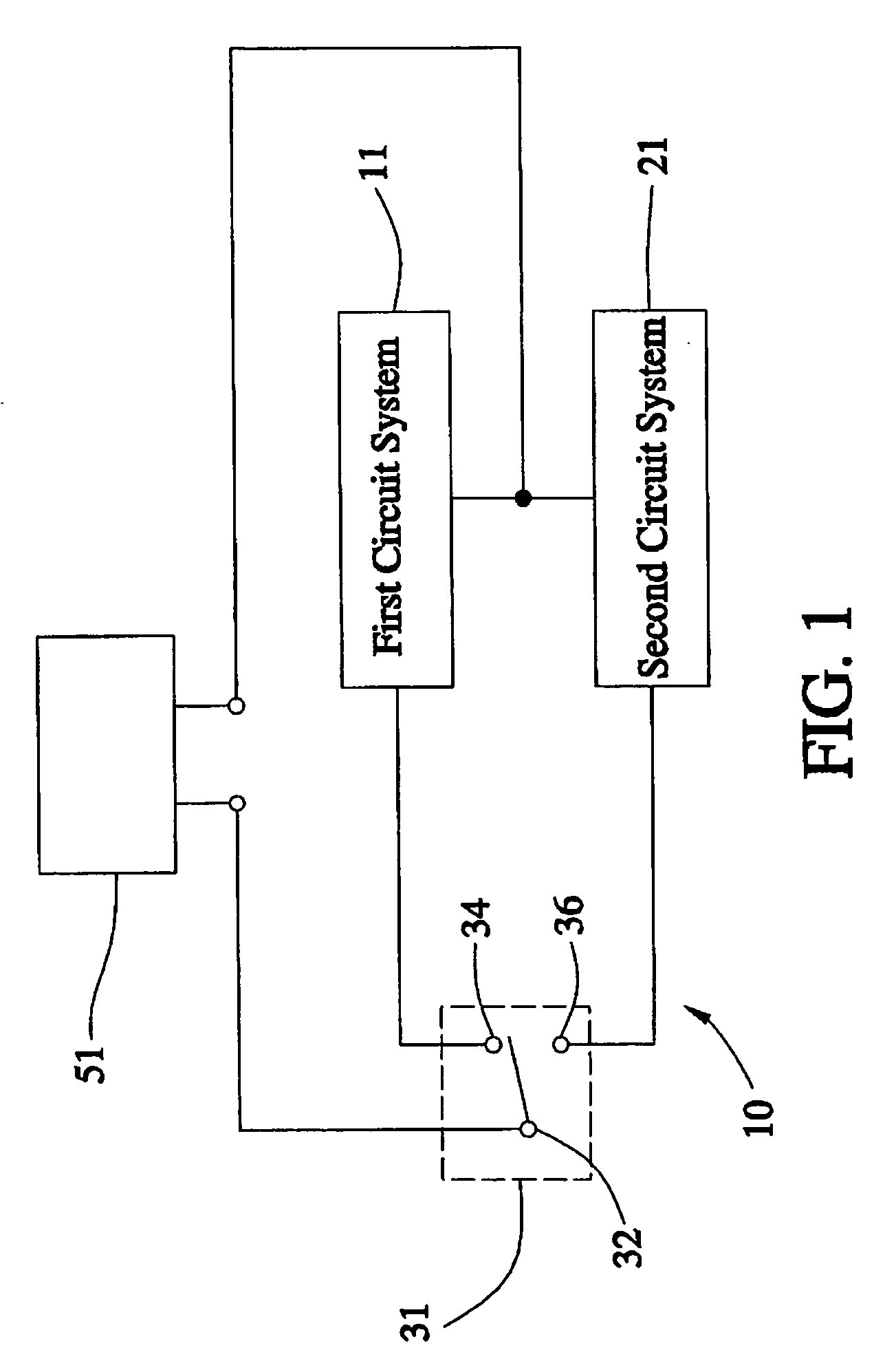
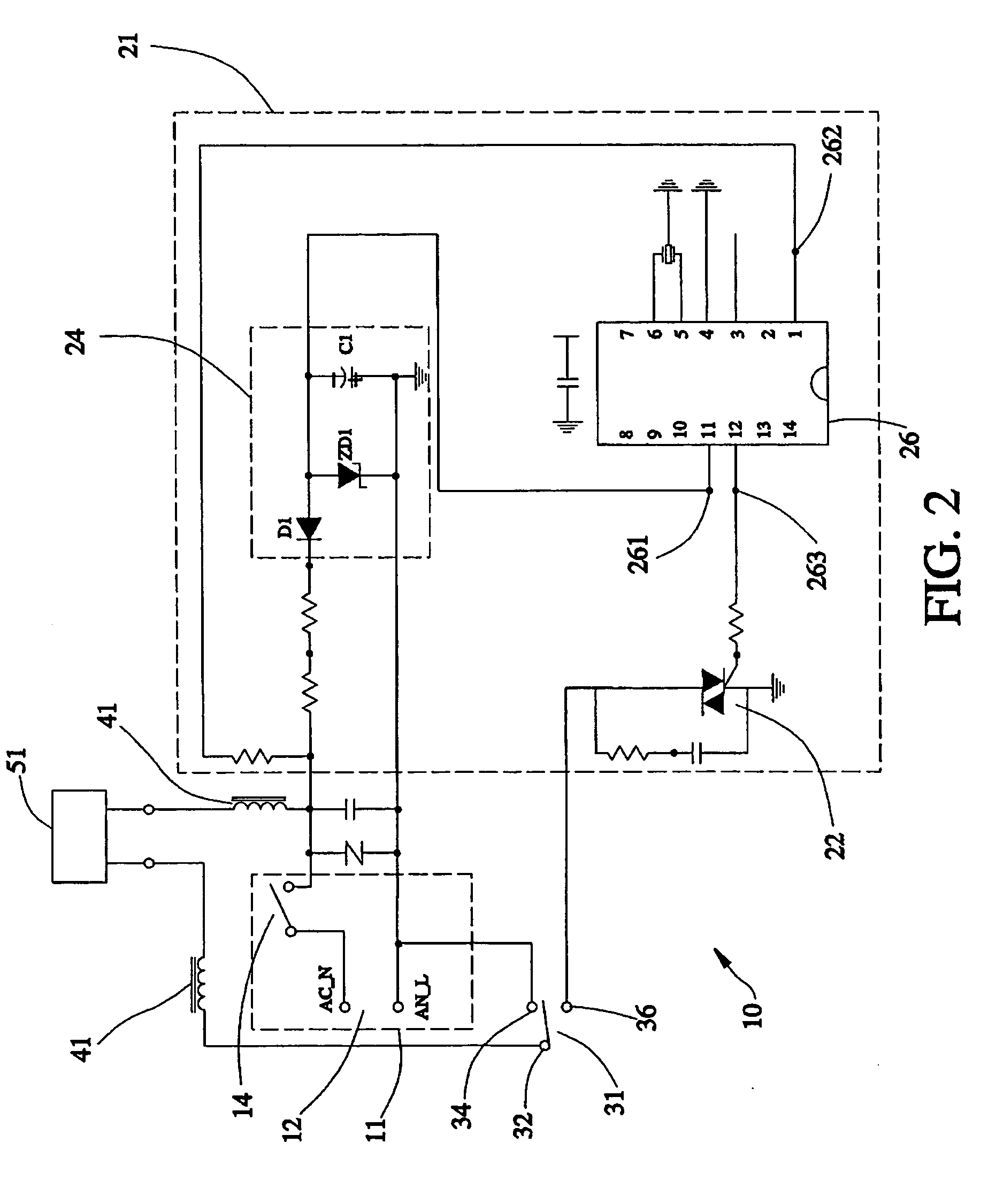
[0012] Referring to FIGS. 1-2, a transmission-controlling device 10 for adjusting the rotational speed of a motor 51 is constructed according to a first embodiment of the present invention. The motor 51 is applied to a power tool (not shown), such as a circular saw machine of a cutting machine, and rotates a cutting blade of the power tool to process a workpiece (not shown). The transmission-controlling device 10 includes a first circuit system 11, a second circuit system 21, and a selective switch 31. The first circuit system 11 has an external power source 12 and a starting switch 14, for providing a first voltage. The external power source 12 provides an alternate current (AC). The starting switch 14 is serially connected with the external power source 12. While the starting switch 14 is short-circuit, the external power source 12 provides the first voltage.

[0013] The second circuit system 21 includes a power semiconductor device 22, a constant-voltage rectifying circuit 24, and...


PUM


Abstract

A transmission-controlling device includes a first circuit system, a second circuit system, and a selective switch. The first circuit system is to provide a first voltage. The second circuit system is to provide a second voltage. The selective switch responds to a user's operation to select the first or second voltage to drive the motor so as to change the rotational speed of the motor. The motor is adapted to a power tool and rotates a cutting blade of said power tool to process a workpiece. Thus, the present invention employs the selective switch to select the driving voltage for the motor to simplify and facilitate the switchover of the rotational speed of the motor.

Description

BACKGROUND OF THE INVENTION [0001] 1. Field of the Invention [0002] The present invention relates to a motor driving a cutting blade of a power tool, and more particularly, to a transmission-controlling device for changing the rotational speed of the motor. [0003] 2. Description of the Related Art [0004] A conventional power tool, such as a circular saw machine or a drilling machine among the woodworking machines, is working by that a motor runs to drive a cutting blade to cut or drill a workpiece. However, the workpiece can be diversified in type and material such that the rotational speed of the motor has to be adjusted according to the material characteristics of the workpiece, while the workpiece is cut or drilled, to enable the cutting blade to cut or drill the workpiece with optimal working efficiency. [0005] To meet the requirement of adjusting the rotational speed of the motor, there are a variety of techniques of controlling the rotational speed. Among the techniques, for e...

Claims


Application Information

Patent Timeline
IPC IPC(8): H02P5/00
CPCH02P25/14
Inventor CHANG, YEN-CHIH
Owner REXON IND CORP LTD
Why Eureka
Eureka Blog
Learn More