
Phase-difference detecting apparatus and method

Inactive Publication Date: 2008-06-05
PROLIFIC TECH INC
View PDF1 Cites 3 Cited by
  • Summary
  • Abstract
  • Description
  • Claims
  • Application Information

AI Technical Summary

Benefits of technology

[0007]The invention is directed to a phase-difference detecting apparatus and method, which can effectively improve the drawbacks of the conventional phase-difference detecting apparatus with lower measurement precision and higher cost.

Problems solved by technology

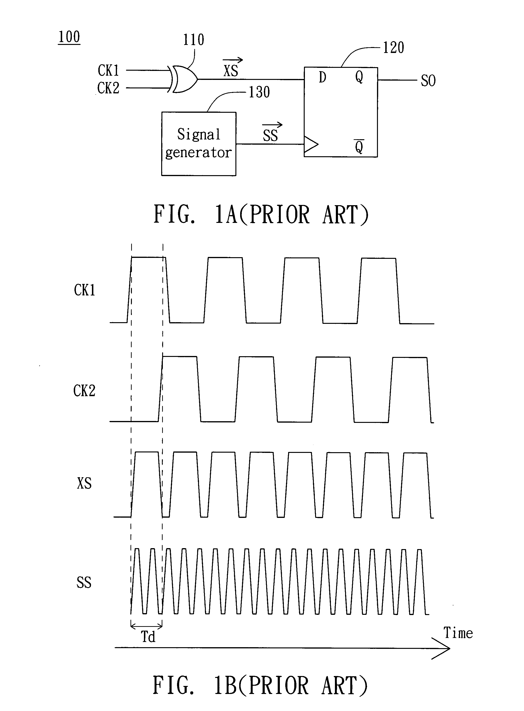
Therefore, in a normal practical application, the phase difference between the timing signals CK1 and CK2 can be only measured by using a measuring signal SS with a frequency slightly higher than those of the timing signals, which results in lower precision of the measurement result.
Besides, to generate the measuring signal SS with a frequency higher than those of the timing signals CK1 and CK2 requires an expensive timing-signal generator 130, which in turn increases the cost of the phase-difference detecting apparatus 100.

Method used


Image

  • Phase-difference detecting apparatus and method
  • Phase-difference detecting apparatus and method
  • Phase-difference detecting apparatus and method

Examples


Embodiment Construction

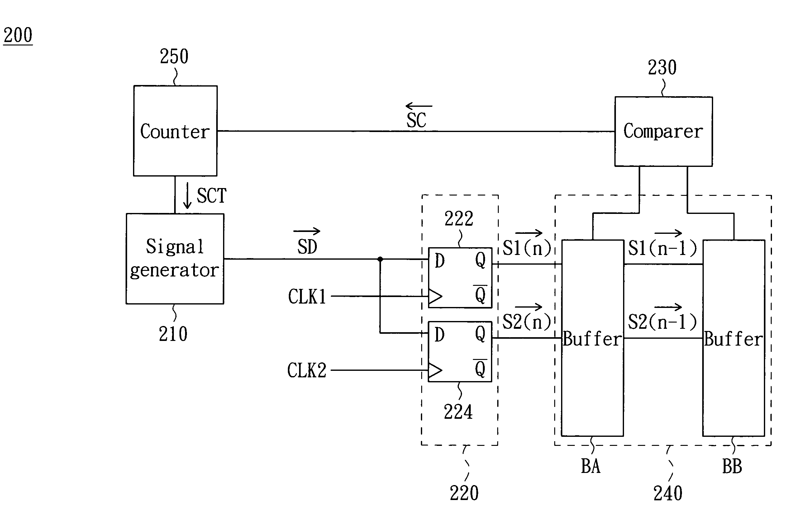
[0017]The phase-difference detecting apparatus and method of the invention sample the detection signal respectively according to two timing signals. The phase-difference detecting apparatus and method of the invention further find out time difference between sample-triggering edges of the two timing signals from sample values of the two timing signals by delaying phase of the detection signal, and obtain the phase difference of the two timing signals according to the time difference.

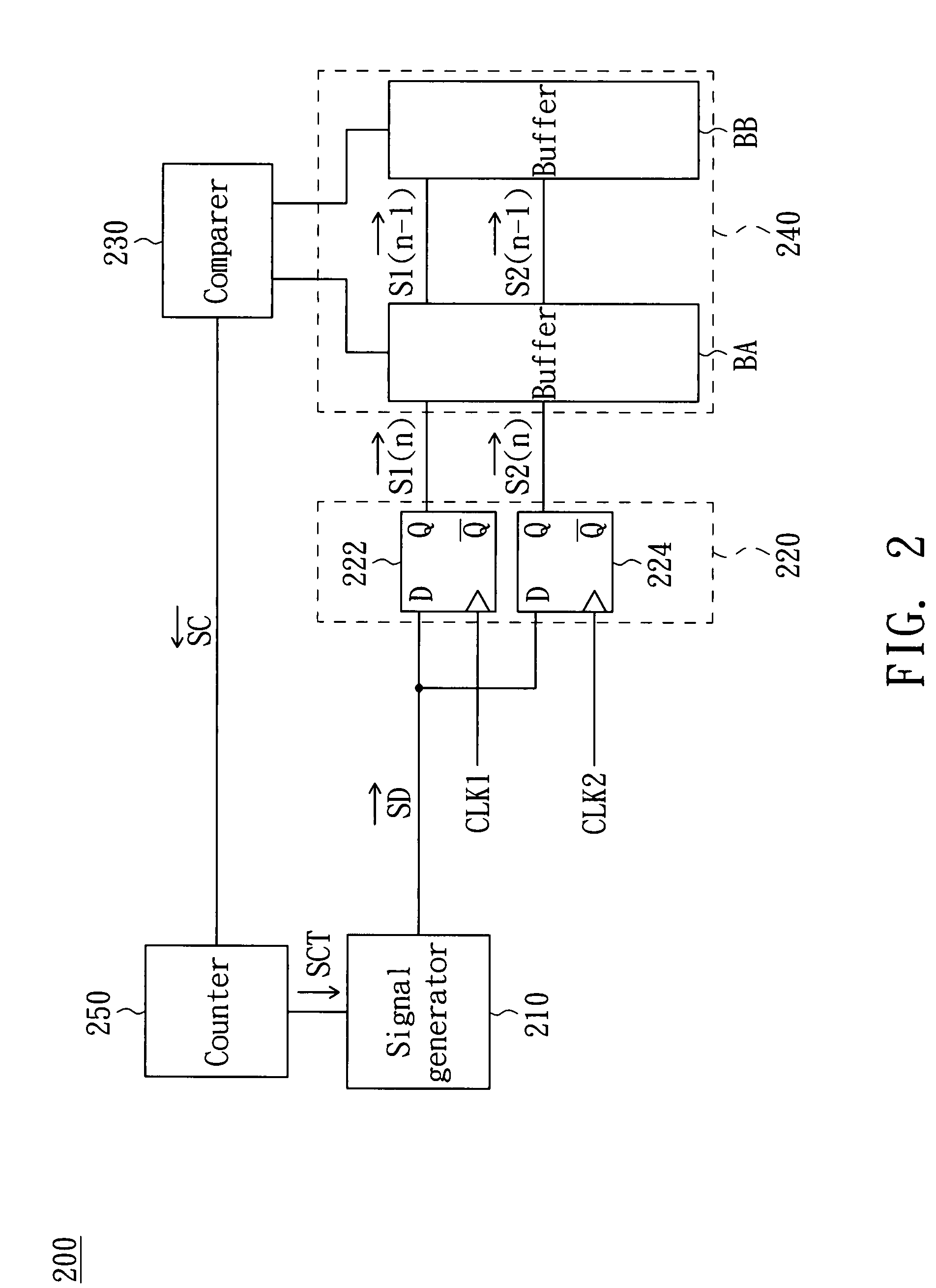
[0018]Referring to FIG. 2, a block diagram of a phase-difference detecting apparatus according to a preferred embodiment of the invention is shown. A phase-difference detecting apparatus 200 includes a signal generator 210, a sample unit 220 and a comparer 230. The signal generator 210 is for generating a detection signal SD and delaying the detection signal SD by a period of fixed time in response to a control signal SC.

[0019]The sample unit 220 is for sampling the detection signal SD respectively accor...


PUM


Abstract

A phase-difference detecting method is for detecting phase difference between a first signal and a second signal of the same frequency. First, generate a detection signal. Next, sample the detection signal respectively according to the first signal and the second signal to obtain a first sample value and a second sample value. Then, determine whether a determination condition that the first and the second sample values are respectively equal to the previous first and second sample values is satisfied. When the determination condition is unsatisfied for the first time, record a delay time of the detection signal as a first time. When the determination condition is unsatisfied for the second time, record a delay time of the detection signal as a second time. Obtain the phase difference between the first signal and the second signal according to the first time and the second time.

Description

[0001]This application claims the benefit of Taiwan application Serial No. 095145027, filed Dec. 4, 2006, the subject matter of which is incorporated herein by reference.BACKGROUND OF THE INVENTION[0002]1. Field of the Invention[0003]The invention relates in general to a phase-difference detecting apparatus, and more particularly to a phase-difference detecting apparatus, which detects phase difference between several targeted signals by delaying the phase of a detection signal.[0004]2. Description of the Related Art[0005]Referring to FIGS. 1A and 1B, a block diagram of a conventional phase-difference detecting apparatus and a timing diagram of relevant signals of the phase-difference detecting apparatus of FIG. 1A are respectively shown. To obtain phase difference between the timing signals CK1 and CK2 with the same frequency and different phases, the timing signals CK1 and CK2 are inputted to an exclusive or (XOR) gate to obtain an exclusive signal XS and the exclusive signal XS a...

Claims


Application Information

Patent Timeline
IPC IPC(8): H03D13/00
CPCH03D13/00
Inventor YEN, MING-HSIENCHEN, HSIN-CHUAN
Owner PROLIFIC TECH INC
Learn More