Vehicle sensor system and process

a technology of vehicle sensor and process, applied in the field of vehicle radar, can solve the problems of inefficient prior art approaches to detecting objects which dwell for a sufficient period, not only to detect objects, but also to calculate target parameters, so as to reduce the expenditure of computational resources and rf emissions, and improve efficiency.

Active Publication Date: 2006-07-13
VEONEER US LLC
View PDF18 Cites 55 Cited by
  • Summary
  • Abstract
  • Description
  • Claims
  • Application Information

AI Technical Summary

Benefits of technology

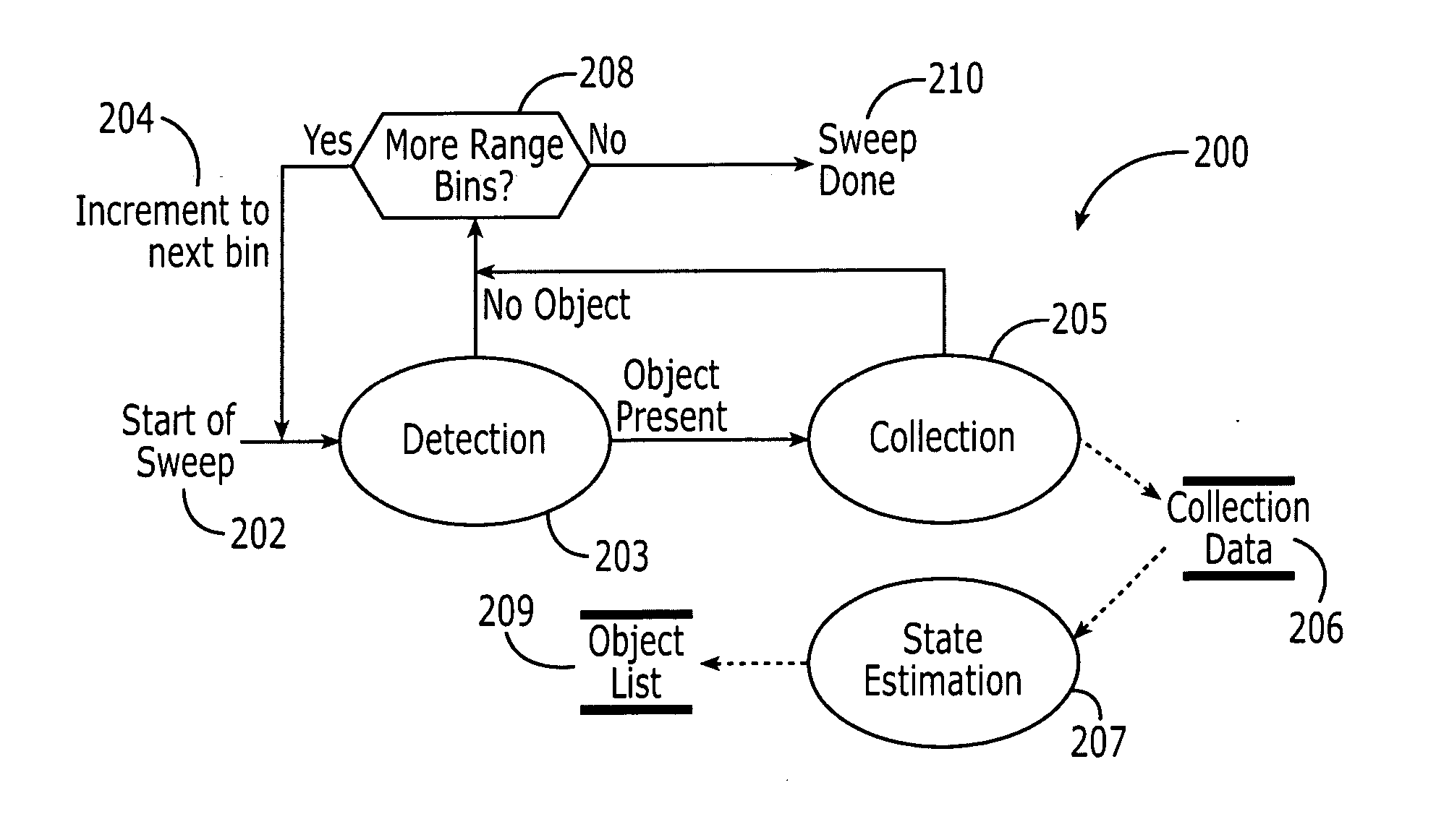
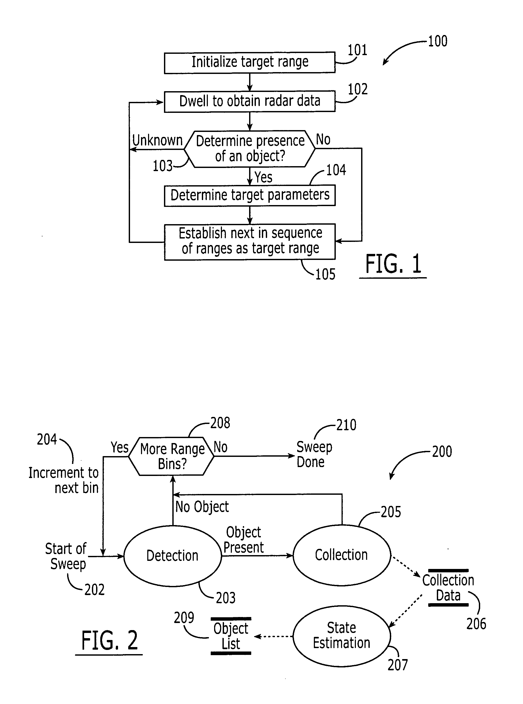
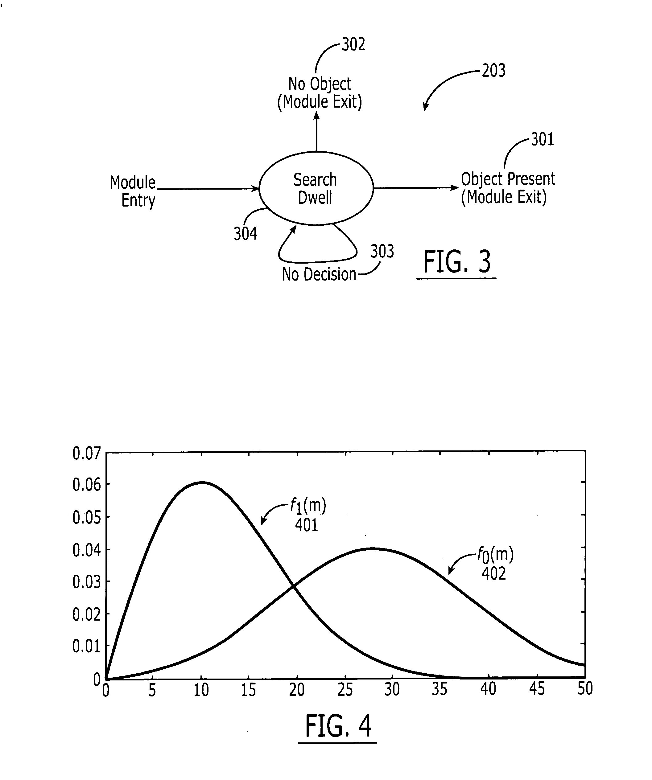
[0007] The present invention provides for a system and process of detecting objects around a vehicle with a reduced expenditure of computational resources and RF emissions. To this end, the system and process of the present invention first determines whether an object is likely to be present at a particular range before dedicating the computational resources and emitting significant RF to determine the target parameters of an object at that range. Specifically, applicants recognize that prior art approaches for detecting objects which dwell for a period that is sufficient, not only to detect the object, but also to calculate its target parameters, are inefficient. To improve efficiency, the applicants apply statistical analysis and probability density distributions to determine whether data obtained initially is consistent with the presence of an object before dwelling longer to determine target parameters.

Problems solved by technology

Specifically, applicants recognize that prior art approaches for detecting objects which dwell for a period that is sufficient, not only to detect the object, but also to calculate its target parameters, are inefficient.

Method used


Image

  • Vehicle sensor system and process
  • Vehicle sensor system and process
  • Vehicle sensor system and process

Examples


Embodiment Construction

[0018] Described herein is a vehicle sensing system and process for determining the presence of objects around the vehicle quickly and accurately. As used herein, the term “vehicle” refers to any primary entity that moves relative to other objects. Preferably, the vehicle carries one or more people for transportation or entertainment purposes. Examples of such vehicles include automobiles (including cars and trucks), airplanes, boats (including personal watercraft, boats, ships and submarines), and railed vehicles (including trains, trolleys and subways). It is also anticipated that the vehicle may be stationary and the objects are moving relative to it (e.g., a toll both). Preferably, the vehicle is an automobile and the present invention is described herein with respect to an automobile.

[0019] As used herein, the term “vehicle sensing system” refers to a vehicle-based sensory system which detects the presence of an object around the vehicle and determines the object's target para...


PUM


Abstract

A process of determining target parameters of an object within a field of detection of an automotive radar system, the process comprising the steps of: (a) establishing a target range from a sequence of ranges; (b) dwelling on the target range for an initial dwell time to obtain sensor data; (c) determining if the sensor data corresponds to the presence of an object or to the absence of an object at the target range based on probability density distributions of an object being present and being absent at the target range, and if such the determination cannot be made, then repeating steps (b)-(c) until the determination can be made; (d) if the sensor data is determined to correspond to the presence of an object in step (c), then dwelling at the target range for an extended dwell time to obtain additional sensor data for determining the target parameters of the object before proceeding to step (e); and (e) establishing the next of the sequence of ranges as the target range before reiterating steps (b)-(e).

Description

CROSS REFERENCE TO RELATED APPLICATIONS [0001] The present application is based on and entitled to the priority of Provisional Application No. 60 / 643,504, filed on Jan. 13, 2005, which is incorporated herein by reference.FIELD OF THE INVENTION [0002] The present invention relates generally to a system and process for detecting the presence of an object around a vehicle, and, more specifically, to a vehicle radar system and process which detects the presence of an object and estimates its parameters with reduced radio frequency (RF) transmissions and computational overhead. BACKGROUND OF THE INVENTION [0003] The popularity of vehicle sensing systems continues to increase. These systems serve to detect and track objects in relation to a moving vehicle. Examples of vehicle sensing systems include radars to support long range applications such as auto cruise control (ACC), and short-range radar (SRR) to support shorter range applications, such as parking aid, stop & go, and pre-crash de...

Claims


Application Information

Patent Timeline
Patent Type & Authority Applications(United States)
IPC IPC(8): G01S13/93G01S13/931
CPCG01S7/292G01S7/2926G01S13/04G01S13/44G01S13/931G01S13/878G01S2013/9375G01S2013/9378G01S2013/9385G01S2013/9325G01S2013/9389G01S2013/93275G01S2013/93274G01S2013/93272G01S2013/93271
Inventor EGRI, ROBERT GYORGYPARADIE, MICHAEL JOHNWEI, SHUANGQUING
Owner VEONEER US LLC
Why Eureka
Try Eureka