Pattern formation method, method for manufacturing color filter, color filter, method for manufacturing electro-optical device, and electro-optical device

a pattern formation and pattern technology, applied in the field of pattern formation, can solve the problems of droplets not spreading out and wetting the entire pattern formation region, droplets leaking into adjacent pattern formation regions, and variance in shape (pattern shape), so as to improve the uniformity of pattern shape and reduce the probability of insufficient wetting by droplets. , the effect of reducing the probability of insufficient wetting

Inactive Publication Date: 2006-07-13
SEIKO EPSON CORP
View PDF2 Cites 7 Cited by
  • Summary
  • Abstract
  • Description
  • Claims
  • Application Information

AI Technical Summary

Benefits of technology

[0010] It is an advantage of the invention to provide a pattern formation method, a method for manufacturing a color filter, a color filter, a method for manufacturing an electro-optical device, and an electro-optical device, with which the volume of droplets discharged into a pattern formation region is determined based on the wettability of the droplets to this pattern formation region, which improves the uniformity of the pattern shape and in turn productivity.
[0011] The pattern formation region of an aspect of the invention includes forming on a pattern formation surface a barrier for forming a pattern; and discharging in a pattern formation region bounded by the barrier droplets containing a pattern formation material, thereby forming the pattern. A lower limit volume of the droplet is determined based on a width in one direction of the pattern formation region and a contact angle of the droplets with respect to the pattern formation surface, such that a volume of the droplet discharged in the pattern formation region is equal to or greater than the lower limit volume.
[0012] With this pattern formation method, since the lower limit volume of the droplet discharged in the pattern formation region is determined based on the contact angle of the droplets to the pattern formation surface, the droplets can reliably wet and spread out over the entire width of the pattern formation region in one direction. As a result, likelihood of insufficient wetting by the droplets can be reduced, and the uniformity of the pattern shape can be improved and the uniformity of the pattern shape can be improved.
[0013] In this pattern formation method, the lower limit volume is preferably a volume at which a distance between an apex of the droplet discharged in the pattern formation region and the pattern formation surface is expressed as: Wa·{(1−cos θa) / sin θa}, where Wa is the width of the pattern formation region in the one direction, and θa is the contact angle of the droplets with respect to the pattern formation surface.
[0014] With this pattern formation method, since the lower limit volume is the volume at which the distance between the apex of a droplet discharged in the pattern formation region and the pattern formation side is Wa·{(1−cos θa) / sin θa}, droplets can be reliably discharged in a volume that allows them to wet and spread out over the entire width of the pattern formation region in the one direction.
[0015] In this pattern formation method, the pattern formation surface is rendered lyophilic to the droplets.

Problems solved by technology

With an inkjet method, however, if the droplets are discharged into the element formation region (pattern formation region) in too small a volume, the droplets will not spread out and wet the entire pattern formation region.
On the other hand, if the droplets are discharged in too large a volume, the droplets will leak out into adjacent pattern formation regions.
In other words, this leads to a variance in the shape (pattern shape) of the organic EL layer formed in the pattern formation region, which is problematic.
However, with JP-A-2000-353594, the volume of the droplets is determined solely on the basis of the shape of the pattern formation region, which leads to the following problems.
Also, if the contact angle of the droplets to the barrier is low, the droplets will tend to leak out, so the volume in which the droplets are discharged must be decreased.
Therefore, if the volume of the droplets is determined solely by the shape of the pattern formation region, inadequate wetting by the droplets and leakage into adjacent pattern formation regions cannot be sufficiently avoided, and will lead to the problem of variance in pattern shape.

Method used


Image

  • Pattern formation method, method for manufacturing color filter, color filter, method for manufacturing electro-optical device, and electro-optical device
  • Pattern formation method, method for manufacturing color filter, color filter, method for manufacturing electro-optical device, and electro-optical device
  • Pattern formation method, method for manufacturing color filter, color filter, method for manufacturing electro-optical device, and electro-optical device

Examples


Embodiment Construction

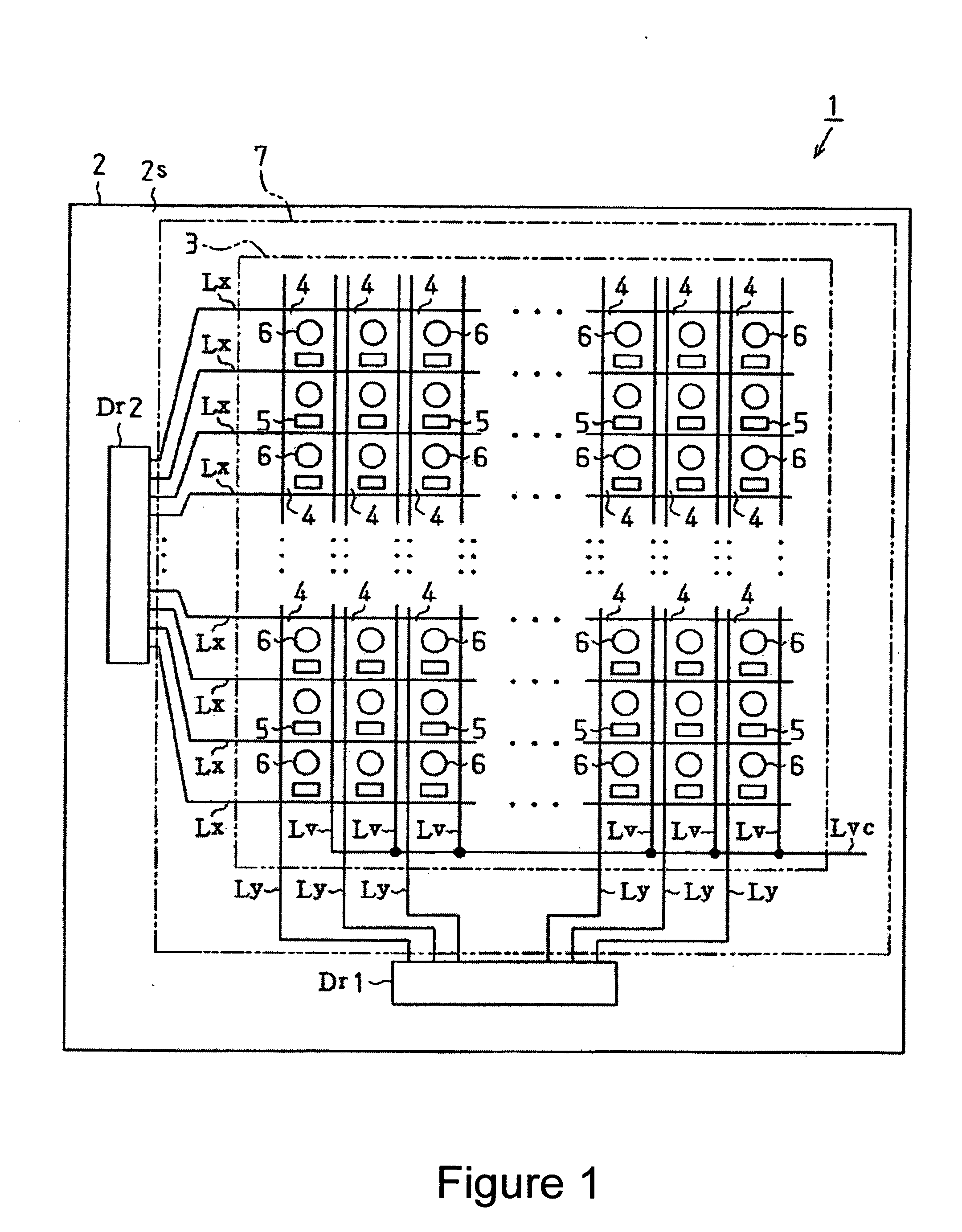
[0046] Embodiments of the present invention will now be described through reference to FIGS. 1 to 9. FIG. 1 is a simplified plan view of an organic electroluminescence display (organic EL display) that serves as an electro-optical device.

[0047] As shown in FIG. 1, an organic EL display 1 is equipped with a transparent substrate 2. The transparent substrate 11 is a non-alkaline glass substrate formed in the shape of a square, and a square element formation region 3 is formed on one side surface thereof (element formation side 2s (the pattern formation side), which is the front side in FIG. 1).

[0048] In this element formation region 3, a plurality of data lines Ly are formed at a specific spacing and extending in the vertical direction (column direction). The data lines Ly are electrically connected to a data line drive circuit Dr1 disposed on the lower side of the transparent substrate 2. The data line drive circuit Dr1 produces a data signal on the basis of display data supplied f...


PUM


Abstract

A pattern formation method includes: forming on a pattern formation surface a barrier for forming a pattern; and discharging in a pattern formation region bounded by the barrier droplets containing a pattern formation material, thereby forming the pattern. A lower limit volume of the droplet is determined based on a width in one direction of the pattern formation region and a contact angle of the droplets with respect to the pattern formation surface, such that a volume of the droplet discharged in the pattern formation region is equal to or greater than the lower limit volume.

Description

BACKGROUND [0001] 1. Technical Field [0002] The present invention relates to a pattern formation method, a method for manufacturing a color filter, a color filter, a method for manufacturing an electro-optical device, and an electro-optical device. [0003] 2. Related Art [0004] Known methods for manufacturing organic electroluminescence elements (organic EL elements) employ a liquid phase process, in which a solution of a macromolecular organic material that will constitute the organic EL element is used to coat an element formation region bounded by a barrier. An inkjet method, which is one of these liquid phase processes, involves discharging the solution in the form of microscopic droplets, and therefore allows the formation of finer organic EL elements than other liquid phase processes (such as spin coating). [0005] With an inkjet method, however, if the droplets are discharged into the element formation region (pattern formation region) in too small a volume, the droplets will n...

Claims


Application Information

Patent Timeline
Patent Type & Authority Applications(United States)
IPC IPC(8): B41J2/17
CPCG02B5/201H01L51/0005H01L51/56H10K71/135H10K71/00F16L1/036F16L1/06F16L9/20
Inventor SAKAI, HIROFUMIKOMORI, SADAHARU
Owner SEIKO EPSON CORP
Why Eureka
Try Eureka