

Illumination attenuation system
- Summary
- Abstract
- Description
- Claims
- Application Information
AI Technical Summary
Benefits of technology
Problems solved by technology
Method used
Image

Examples
Embodiment Construction
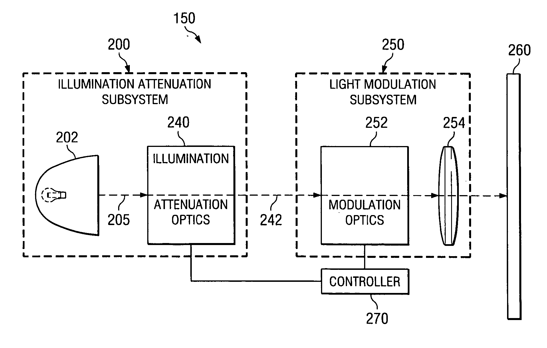
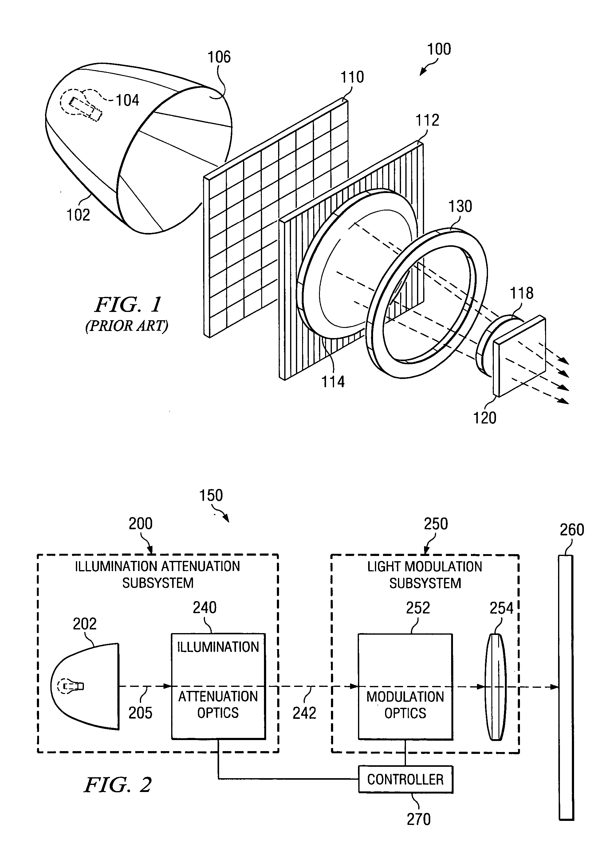
[0023]FIG. 2 illustrates a schematic diagram of a projection system 150. Projection system 150 includes an illumination attenuation subsystem 200 optically coupled to a light modulation subsystem 250. Projection system 150 may also include a controller module 270 coupled to the illumination attenuation subsystem 200 and light modulation subsystem 250.
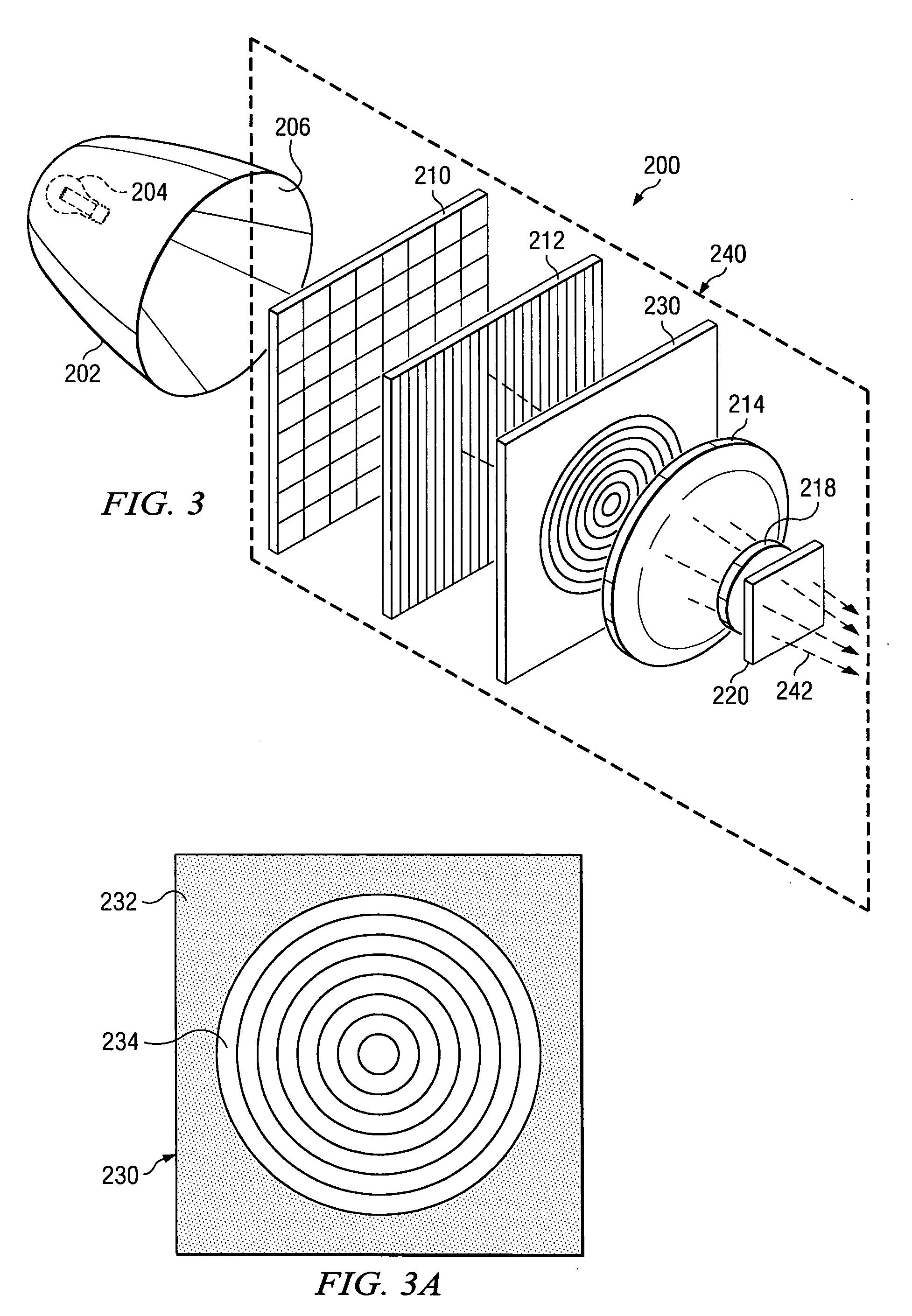
[0024] The illumination attenuation subsystem 200 is located in the light path of projection display system 150 ahead of a light modulation subsystem 250. The illumination attenuation subsystem 200 is operable to attenuate the light 205 from the light source 202 according to image characteristics. The illumination attenuation subsystem 200 includes an attenuation control input in communication with an image controller in controller module 270. The illumination attenuation subsystem 200 also includes a liquid crystal panel in illumination attenuation module 240 that may modulate light in the light path. The illumination attenuation subs...
PUM
 Abstract
Description
Claims
Application Information