Image forming method and image forming device

a technology of image forming and forming method, which is applied in the direction of digital output to print units, corona discharge, instruments, etc., can solve the problems of deterioration of developer, lowering image quality, and increasing toner density, so as to achieve the effect of stabilizing the developmentability

Inactive Publication Date: 2006-07-13
SHARP KK
View PDF14 Cites 28 Cited by
  • Summary
  • Abstract
  • Description
  • Claims
  • Application Information

AI Technical Summary

Benefits of technology

[0020] The present invention has been made with the aim of solving the above problems, and it is an object of the present invention to provide an image forming method and an image forming apparatus capable of holding a toner density appropriately, stabilizing the developability and forming a satisfactory image by correcting a toner density reference value based on a correction value of the currently set value with respect to an initial value of the set value of an image forming condition to accurately meet an environment change of humidity.
[0021] Another object of the invention is to provide an image forming method capable of holding the toner density appropriately, stabilizing the developability and forming a satisfactory image by correcting a toner density reference value against changes in the toner density and developability caused by a difference in the frequency of use of an image forming apparatus.
[0022] Still another object of the invention is to provide an image forming method capable of preventing a decrease in the efficiency of printing operation of an image forming apparatus and an abrupt change in the printed image density by making the correction at one time when performing the correction to decrease the supply amount of toner, or making the correction gradually when performing the correction to increase the supply amount of toner.

Problems solved by technology

However, since the two-component developer has an environmental dependency, in a high humidity state, the toner density in the developer increases and the charge amount decreases, and consequently toner scattering, adhesion of toner in a non-image area, a broken image, etc. occur, and the image quality is lowered.
Moreover with an increase in the copy volume and an increase in the developer agitation time, the developer deteriorates, the toner density increases compared to the initial density (at the time the apparatus was installed and the developer was replaced) due to this deterioration, and the charge amount decreases.
Consequently, toner scattering, adhesion of toner to a non-image area, a broken image, etc., occur, and there arises a problem that the image quality is lowered.
Consequently, toner scattering, adhesion of toner to a non-image area, a broken image, etc. occur, and there arises a problem that the image quality is lowered.
However, this image forming apparatus does not take into account an increase in the output voltage value of the ATC sensor 10 caused by the above-mentioned spent toner.
In other words, even when the agitation time increases, if the humidity decreases, control is performed to decrease the reference output voltage value without considering the influence of spent toner, and consequently there arises a problem that the toner density increases.
Moreover, there is a difference in the agitation stress of developer per unit time depending on the frequency of use of the image forming apparatus for copying or printing by the user.

Method used


Image

  • Image forming method and image forming device
  • Image forming method and image forming device
  • Image forming method and image forming device

Examples


embodiment 1

[0127]FIG. 4 is a cross sectional view showing an image forming apparatus of Embodiment 1 of the present invention.

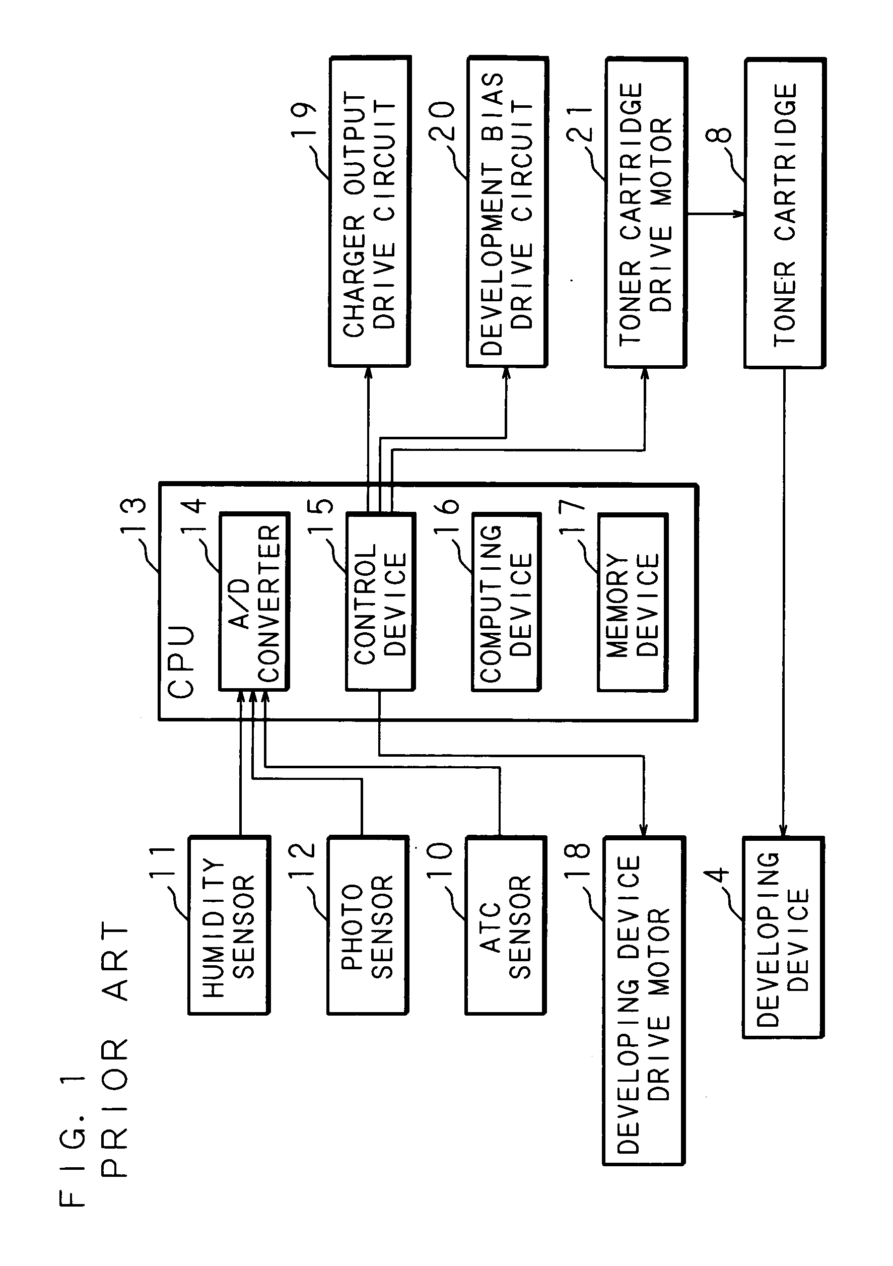
[0128] This image forming apparatus comprises a photoreceptor drum 1, a charging device 2, an exposure device 3, a developing device 4, a transfer device 5, a sheet feeding device 6, a fixing device 7, a toner cartridge 8, a cleaning device 9, an ATC sensor 10, a humidity sensor 11, and a photo sensor 12.

[0129]FIG. 5 is a block diagram showing the structure of the image forming apparatus of Embodiment 1 of the present invention.

[0130] A CPU 13 constituting a control unit comprises an A / D converter 14 for converting analog output voltage values of the ATC sensor (toner density sensor) 10, humidity sensor 11 and photo sensor 12 into digital output voltage values; a control device 15 for controlling a charger output drive circuit 19, a development bias drive circuit 20, a developing device drive motor 18 and a toner cartridge drive motor 21; a memory device 17; and a co...

embodiment 2

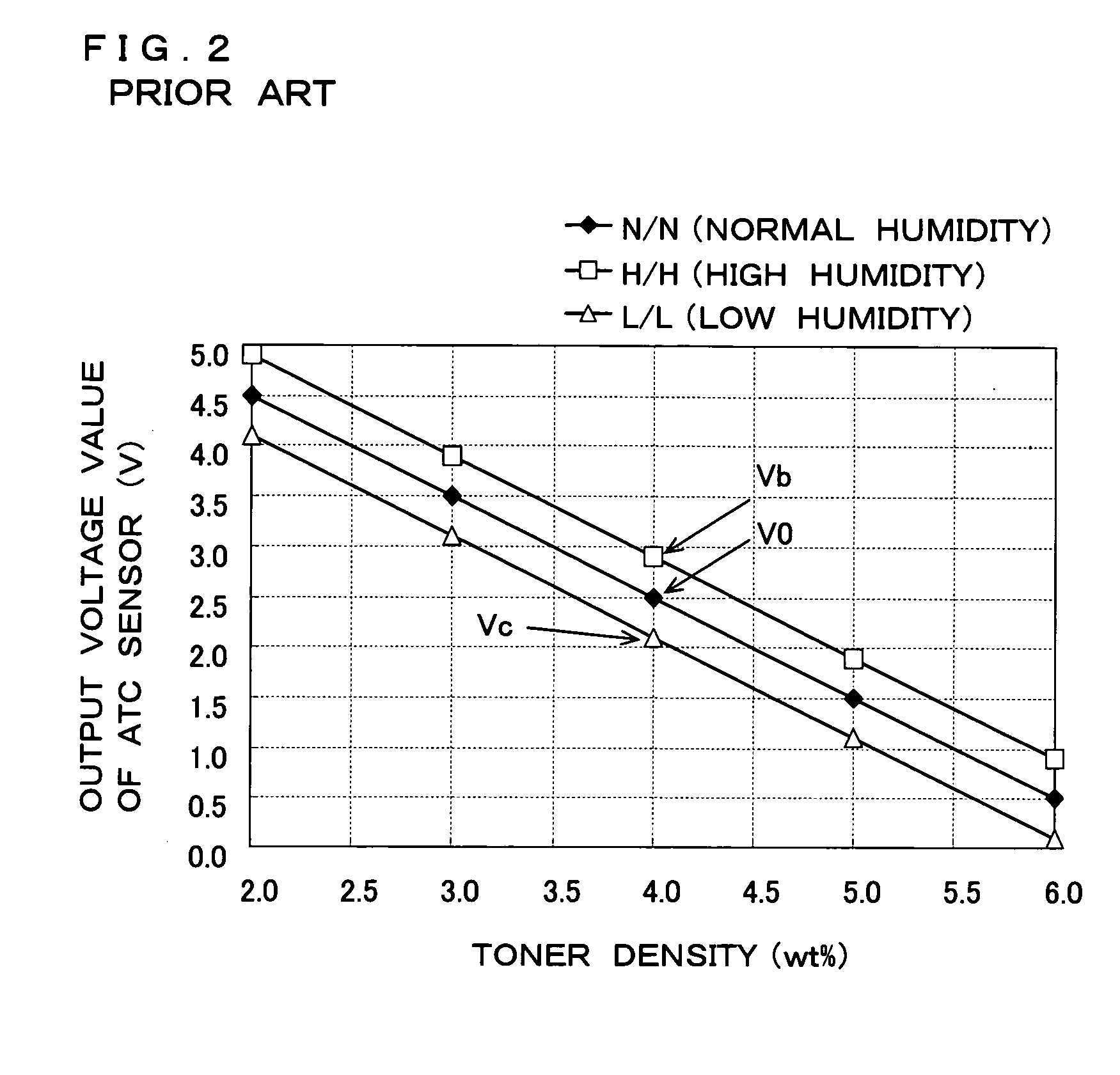
[0212] There is a difference in the agitation stress of developer per unit time depending on the frequency of use of the apparatus for copying or printing by the user. The difference in the agitation stress of developer per unit time causes a difference in the charge amount of toner, and consequently causes a difference in the output voltage value of the ATC sensor 10 regardless of the same toner density. In the developer of an apparatus of low frequency of use where the agitation stress per unit time is small, the toner density increases, the charge amount decreases, and the image quality is lowered due to occurrence of toner scattering, adhesion of toner to a non-image area, a broken image, etc. On the other hand, in the developer of an apparatus of high frequency of use where the agitation stress per unit time is large, the toner density decreases, the charge amount increases, the image density decreases, and the image quality is lowered due to occurrence of blurred characters, f...

embodiment 3

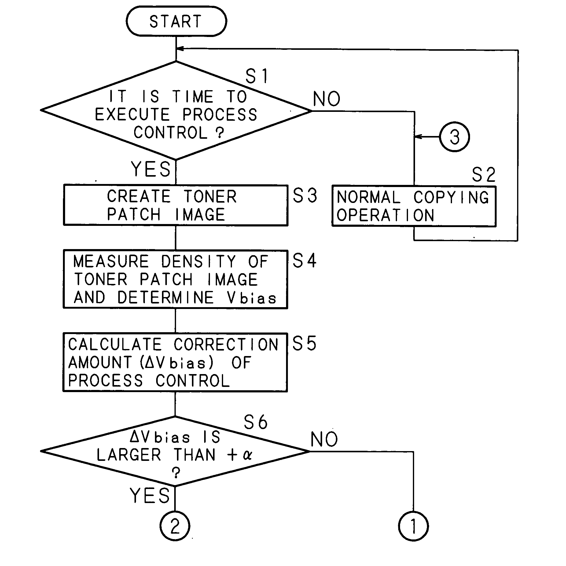
[0240]FIG. 20 through FIG. 22 show a flowchart illustrating the processing steps of correcting the reference output voltage value based on a humidity change and the frequency of use of the apparatus by the control device 15 of Embodiment 3.

[0241] When the power supply is turned on to start processing, the CPU 13 of the image forming apparatus determines whether or not it is the time to execute the process control (step S51). The time to execute the process control is the time at which control is necessary, such as when the power supply is turned on, after elapse of a predetermined time since the power supply was turned on, or a preset timing such as after finishing a predetermined number of copies.

[0242] In step S51, when a determination is made that it is not the time to execute the process control, the normal copying operation is repeated until the execute time (step S52).

[0243] In step S51, when a determination is made that it is the time to execute the process control, a tone...


PUM


Abstract

A reference developing image is formed on a photoreceptor drum under an image forming condition measured in advance, and the density of this reference developing image is detected. A development bias voltage is corrected based on the detection result, and when a correction value of the development bias voltage exceeds a predetermined range, a reference output voltage of an ATC sensor for detecting the density of toner in a developing device is corrected based on the detected value of humidity around the developing device, the frequency of use of the apparatus, and the agitation stress of developer.

Description

[0001] This application is the national phase under 35 U.S.C. § 371 of PCT International Application No. PCT / JP2004 / 002590 which has an International filing date of Mar. 2, 2004 and designated the United States of America. TECHNICAL FIELD [0002] The present invention relates to an image forming method and an image forming apparatus such as an electrophotographic type copying machine, a laser printer or a facsimile machine for use in implementing the image forming method, and more particularly relates to an image forming method and an image forming apparatus including toner density detecting means for measuring the permeability of developer in a developing device for developing an electrostatic latent image by a two-component developer composed of toner and carrier, and controlling the amount of toner supplied to the developing device, based on the difference between an output voltage value corresponding to the toner density detected by the toner density detecting means and a referen...

Claims


Application Information

Patent Timeline
Patent Type & Authority Applications(United States)
IPC IPC(8): H04N1/46G03G9/09G03G9/08G03G15/00G03G15/06G03G15/08
CPCG03G15/065G03G2215/00037
Inventor ITOYAMA, MOTOYUKIFUJITA, SYOUICHISAKITA, HIROFUMIMORIKUNI, SHUICHI
Owner SHARP KK
Why Eureka
Try Eureka