Image-taking device

a technology of image-taking device and shake correction section, which is applied in the direction of exposure control, printing, instruments, etc., can solve the problems of large shake, large shake, and inability to accurately correct shake, so as to achieve the effect of using the shake correction section and shooting an image with little blur

Inactive Publication Date: 2006-07-13
FUJIFILM HLDG CORP +1
View PDF8 Cites 13 Cited by
  • Summary
  • Abstract
  • Description
  • Claims
  • Application Information

AI Technical Summary

Benefits of technology

[0024] According to the image-taking device of the present invention, it is possible to achieve effective use of the shake correcting section and thereby to shoot an image with little blur.

Problems solved by technology

In these image-taking devices, the shift lens has a limitation in terms of the moving range for correcting shakes.
Here, a large shake may occur and such a shake may exceed the moving range.
There is also a limitation in terms of response of a driving section including the shift lens.
For this reason, when shakes occur frequently, such a mechanism may fail to follow the shakes.
As described above, a conventional image-taking device may include the shake correcting section but may still cause a blurry photograph when an image is shot at the time of a large shake or in the course of frequent shakes.
Accordingly, such a conventional image-taking device has a problem in making effective use of the shake correcting section.

Method used


Image

  • Image-taking device
  • Image-taking device
  • Image-taking device

Examples


first embodiment

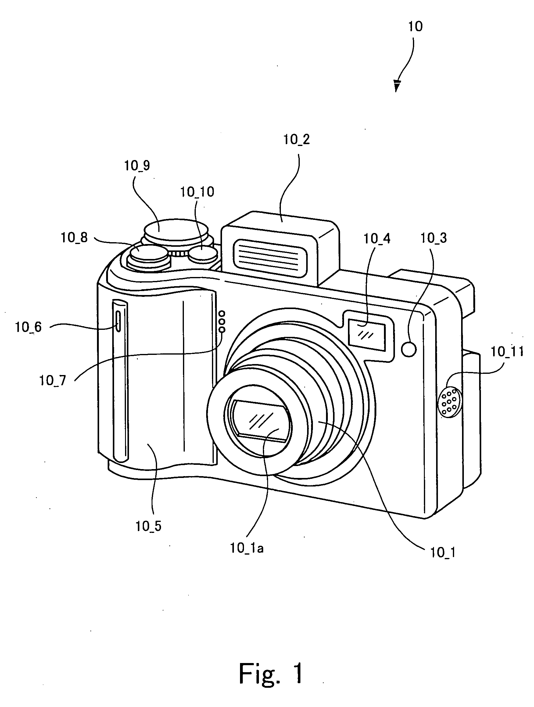
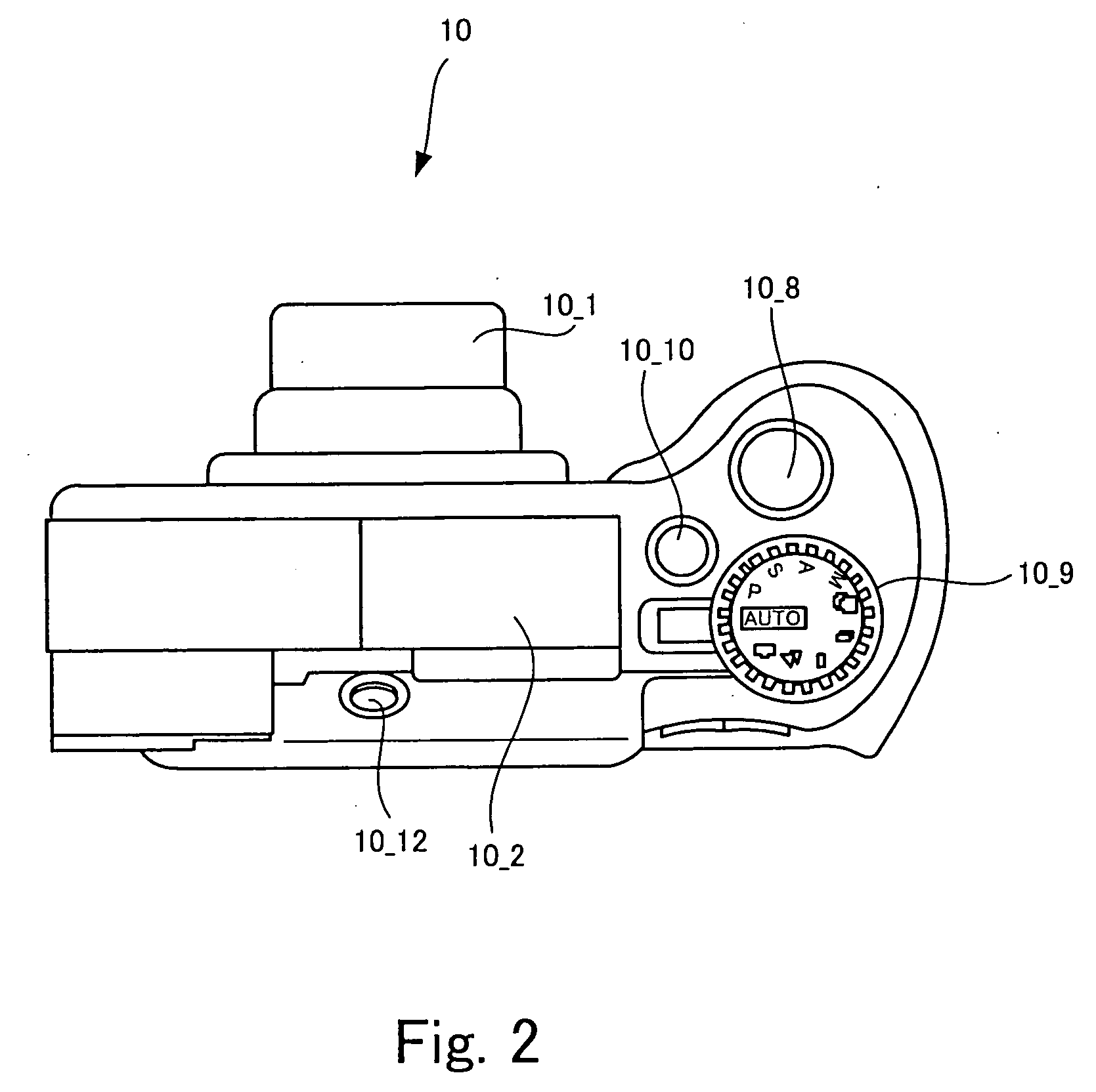
[0040]FIG. 1 is an external perspective view of a digital camera representing an image-taking device according to the present invention, which is viewed obliquely from above and from a front side.

[0041] A digital camera 10 shown in FIG. 1 is an image-taking device configured to form an object image on an image pickup device by use of an image-taking optical system and to generate an image signal for recording in response to a shooting instruction, which includes a shake correcting section which corrects a shake when shooting an image. The shake correcting section will be described later.

[0042] A zoom lens barrel 10_1 incorporating a shooting lens 10_1a being an optical zoom lens is disposed at a central part on a front face of the digital camera 10 shown in FIG. 1. Moreover, a flash light emission device 10_2 which emits flash light synchronously with a shooting operation, a flash light adjustment sensor 10_3 which detects an amount of the flash light for controlling the amount of ...

second embodiment

[0104]FIG. 11 is a block diagram showing a circuit configuration of a digital camera representing an image-taking device according to the present invention.

[0105] Here, external views of a digital camera 20 are the same as the external views of the digital camera 10 as shown in FIGS. 1, 2, and 3. Accordingly, illustration of the external views will be omitted herein.

[0106] As compared to the circuit configuration of the digital camera 10 shown in FIG. 4, the circuit configuration of the digital camera 20 shown in FIG. 11 has differences in a shift lens driving section 20_56 and a CPU 20_47.

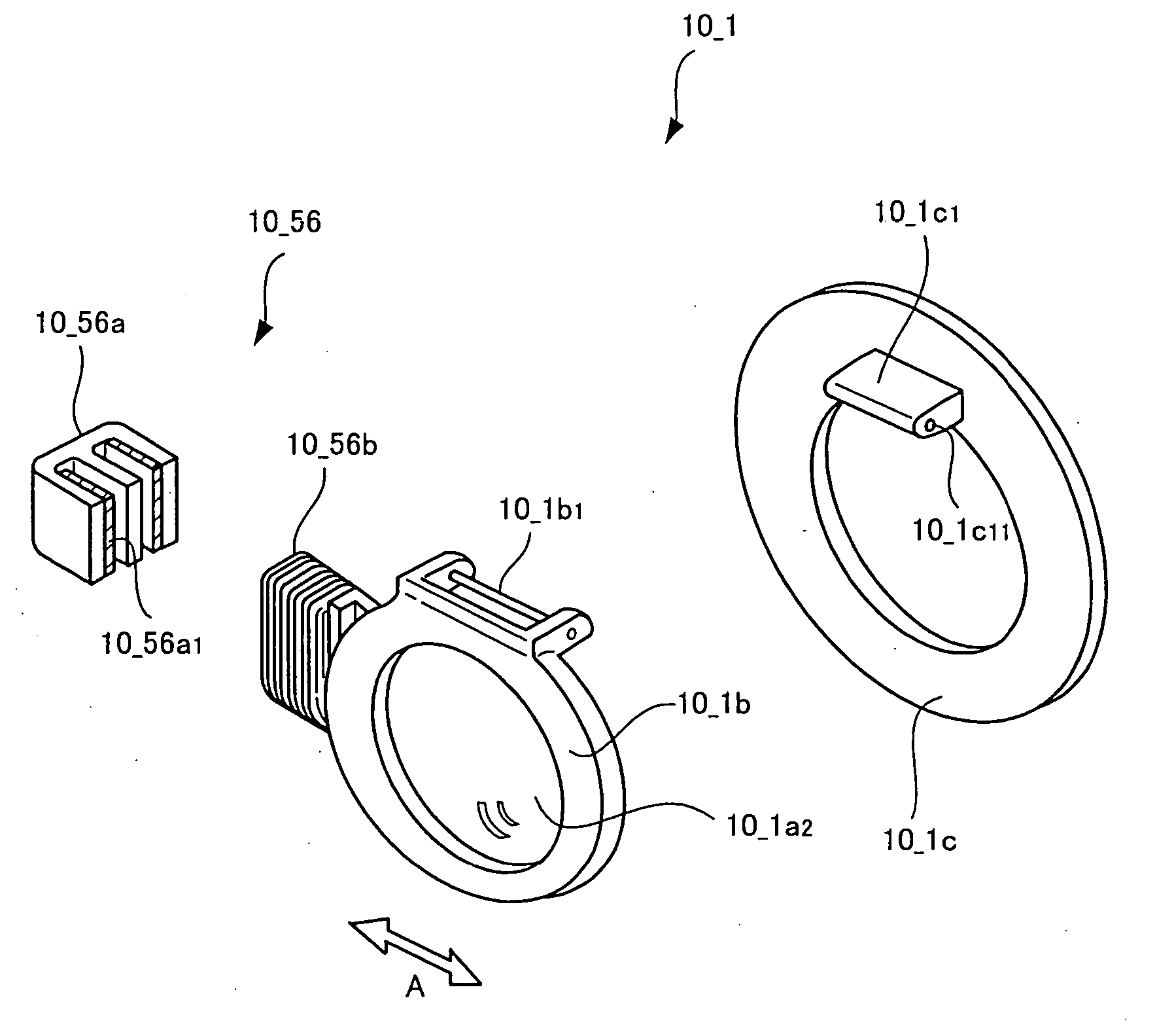
[0107] The shift lens driving section 20_56 is configured to pull the shift lens 10_1a2, which has moved to a biased position from a predetermined center, back to the center after shooting an image by use of a pullback force corresponding to the distance between the position of the moved shift lens 10_1a2 and the center.

[0108] Meanwhile, the CPU 20_47 plays a role of calculating the correction ...

third embodiment

[0125]FIG. 13 is a block diagram showing a circuit configuration of a digital camera representing an image-taking device according to the present invention.

[0126] Here, external views of a digital camera 30 are the same as the external views of the digital camera 10 as shown in FIGS. 1, 2, and 3. Accordingly, illustration of the external views will be omitted herein. As compared to the circuit configuration of the digital camera 10 shown in FIG. 4, the circuit configuration of the digital camera 30 shown in FIG. 13 has differences in an angular rate sensor 30_55, a shift lens driving section 30_56, and a CPU 30_47. Here, the angular rate sensor 30_55, the shift lens 10_1a2, the shift lens driving section 30_56, the CPU 30_47, and the liquid crystal monitor 10_34 collectively constitute another example of the shake correcting section of the present invention, which has the correction effects at different levels depending on a frequency of the shake.

[0127] The angular rate sensor 30_...


PUM


Abstract

An image-taking device is capable of effectively utilizing a shake correcting section and thereby shooting an image with little blur. The image-taking device includes: an angular rate sensor which detects a shake; a shift lens which travels within a predetermined moving range to correct the shake; a shift lens driving section which pulls the shift lens, which has moved to a biased position from a predetermined center, back to the center; a central processing unit which calculates a correction effect for the shake; and a liquid crystal monitor. The central processing unit calculates the correction effect based on a distance between the position of the moved shift lens and the center, and displays the correction effect on the liquid crystal monitor.

Description

BACKGROUND OF THE INVENTION [0001] 1. Field of the Invention [0002] The present invention relates to an image-taking device configured to focus an object image on an image pickup device by use of an image-taking optical system and to generate an image signal for a recording purpose in response to a shooting instruction. [0003] 2. Background of the Related Art [0004] Image-taking devices such as digital cameras or video cameras including shake correcting sections for correcting shakes at the time of shooting images have heretofore been diffused. A shake correcting section for instance includes a lens member (a shift lens) disposed in the way of a light path of light from an object which is incident on an image pickup device, and an angular rate sensor such as a vibration gyro-sensor. An image-taking device including this shake correcting section is configured to correct shakes at the time of shooting images by moving the shift lens within a given moving range and thereby displacing a...

Claims


Application Information

Patent Timeline
Patent Type & Authority Applications(United States)
IPC IPC(8): G03B17/00
CPCG03B5/04
Inventor MISAWA, ATSUSHIMIYAISHI, HITOKI
Owner FUJIFILM HLDG CORP
Why Eureka
Try Eureka