Instrument guide and implant holder

a technology of instruments and holder, which is applied in the field of medical instruments, can solve the problems of increased difficulty in maneuvering, increased difficulty in operating room, and increased difficulty for surgeons to maneuver, so as to facilitate the insertion of variable angle bone screws and maintain visibility in the operating region.

Inactive Publication Date: 2006-07-13
THEKEN SPINE
View PDF1 Cites 46 Cited by
  • Summary
  • Abstract
  • Description
  • Claims
  • Application Information

AI Technical Summary

Benefits of technology

[0010] Accordingly, the present invention is directed to an instrument guide and implant holder that can securely and accurately position a bone plate or implant at a target location, while also providing a guide mechanism for properly drilling or tapping a bone screw hole and threading a bone screw into said hole. Use of the present invention allows the surgeon to securely hold the plate at its proper location for insertion into the surgical opening, while still maintaining visibility in the operating region. The present invention is directed to any form of impla...

Problems solved by technology

This text discusses the fact that severe complications associated with procedures involving the upper cervical spine can be catastrophic, including injuries to the brain stem, spinal cord, or vertebral arteries, not to mention damage to the esophagus.
In procedures involving the cervical spine, additional difficulties are encountered as a direct result of the small space in which the surgeon has to operate.
When the upper cervical area is dissected, surgeons often find it difficult to maneuver because dissection is intimately close to vital neural, vascular, and visceral structures.
As a result, surgeons have little room to operate, and even less room to manually position bone implant structures.
In certain procedures requiring variable angle fixation (that is, insertion of fasteners that are allowed to have varying angles of entry to allow settling and movement in situ) surgeons sometimes have difficulty maint...

Method used


Image

  • Instrument guide and implant holder
  • Instrument guide and implant holder
  • Instrument guide and implant holder

Examples


Embodiment Construction

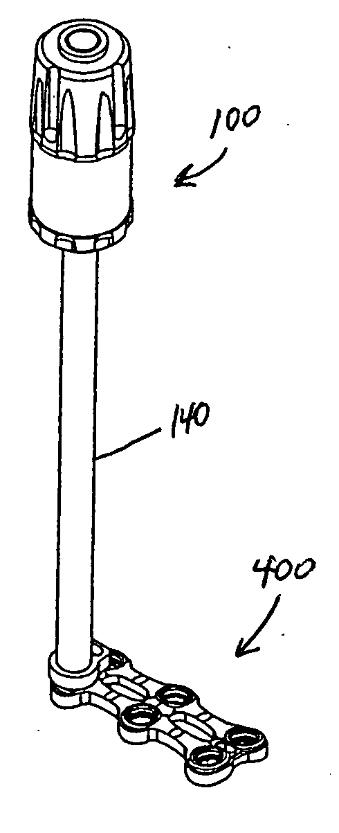
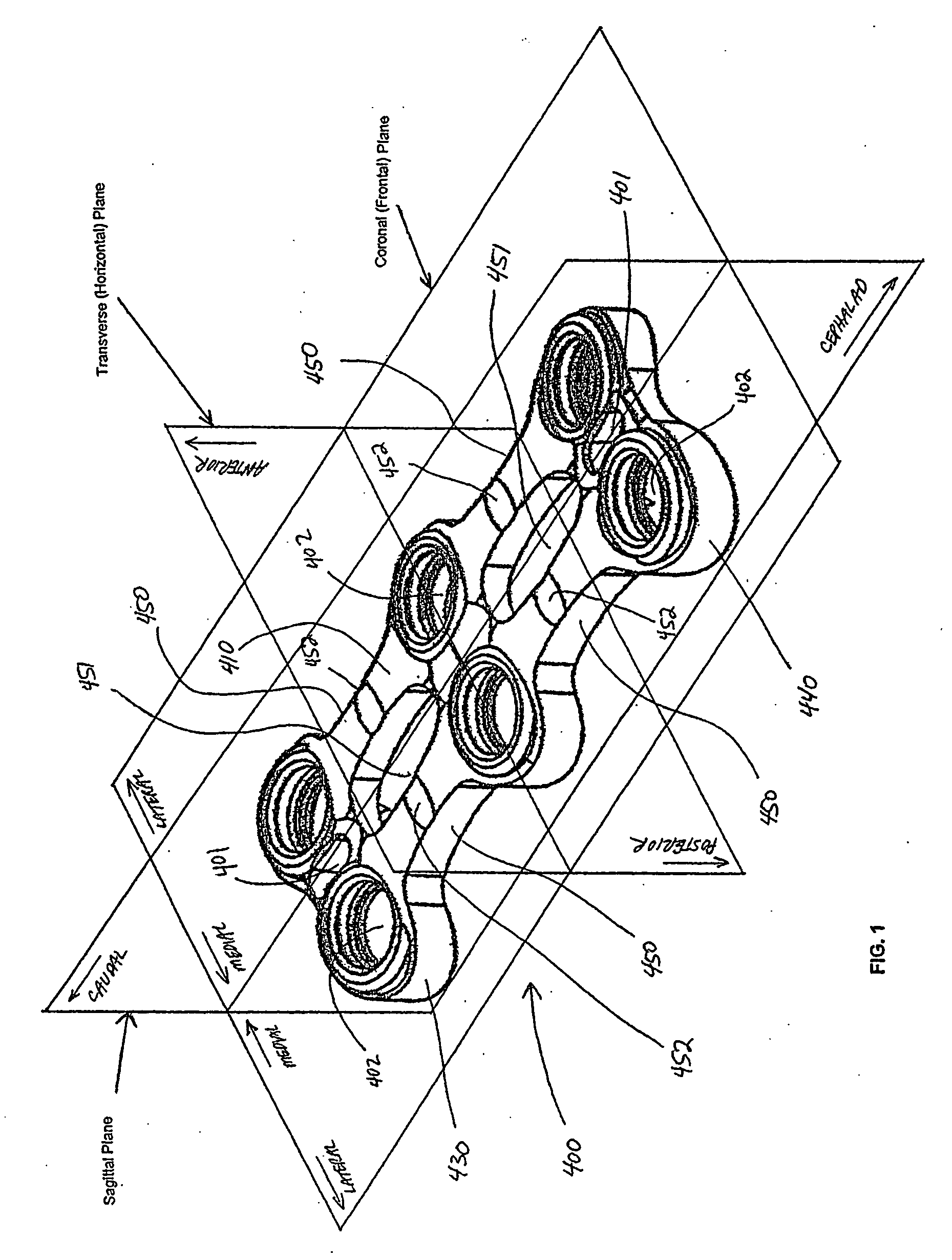
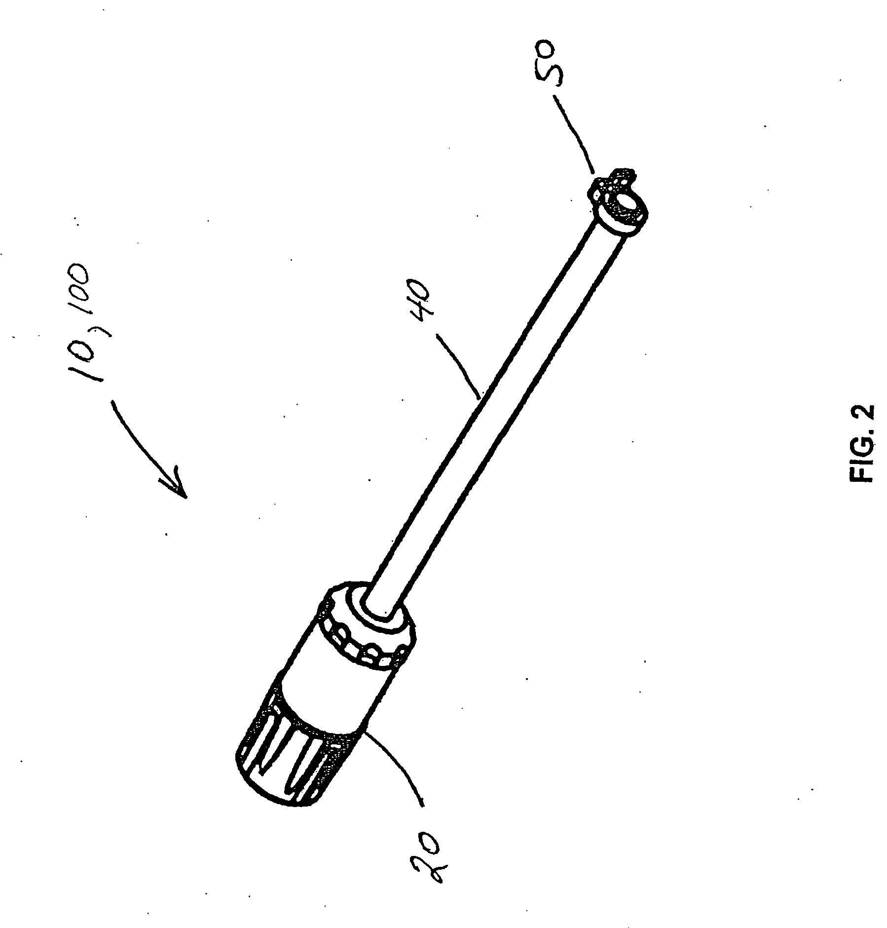
[0082] While the present invention will be described more fully hereinafter with reference to the accompanying drawings, in which particular embodiments and methods are shown, it is to be understood from the outset that persons of ordinary skill in the art may modify the invention herein described while achieving the functions and results of this invention. Accordingly, the descriptions which follow are to be understood as illustrative and exemplary of specific embodiments within the broad scope of the present invention and not as limiting the scope of the invention. For instance, words such as “bone implant”, are used in the general sense and can include bone plates, bone cages, and any other implantable device. Similarly, for ease of description, the following description refers to bone screws. It should be understood, however, that any fastener that is suitable for implantable devices may be substituted for the screw that is described herein, to the extent that such substitution ...


PUM


Abstract

An instrument guide and implant holding device is provided which releasably secures an implant to the instrument guide. The device provides a convenient guide for surgeons to perform various operative techniques on the subject bone without the need for separate devices, and allows all these operative techniques to be performed without removing the instrument guide from the dissected area until all operative techniques have been completed. The releasable mechanism allows the surgeon to easily hold the instrument to an implant using a simple press-fit approach, and easily releases from the implant with a minimal amount of force. An embodiment also allows the surgeon to releasably lock the cannula in a given orientation about the centroidal axis of the implant fastener hole.

Description

CROSS-REFERENCE TO RELATED APPLICATION [0001] This application is a divisional application of and claims priority to co-pending patent application Ser. No. 10 / 384,202, filed on Mar. 7, 2003.BACKGROUND OF THE INVENTION [0002] The present invention relates generally to medical instrumentation for implanting medical devices. More particularly, the invention relates to an instrument guide and holder assembly that can be used in conjunction with orthopedic plate systems. [0003] In the art of orthopedic fixation, it has become common for surgeons to utilize fixation plates for the treatment of spinal disorders including spinal anomalies, spinal injuries, disc problems, and bone problems. Indeed, within the past several years, the use of fixation plates for the treatment of spinal disorders or for fusion of vertebrae has grown considerably, and spinal plates have found increased use and desirability in the cervical spine as well. [0004] As adequately described by Dr. Howard S. An and Dr. J...

Claims


Application Information

Patent Timeline
IPC IPC(8): A61F2/36
CPCA61B17/1728A61B17/7059A61B17/8085A61B17/809A61B2017/0046A61B17/1757
Inventor MUELLER, RICHARDTHEKEN, RANDALL R.ALBERT, MORTON B.
Owner THEKEN SPINE
Why Eureka
Try Eureka