Method and apparatus for supporting verification, and computer product

a verification method and verification technology, applied in the field of supporting verification, can solve the problems of disadvantageous insufficient verification, hardly sufficient, unrealistic way of executing the pattern on all combinations,

Inactive Publication Date: 2006-07-13
FUJITSU LTD
View PDF5 Cites 30 Cited by
  • Summary
  • Abstract
  • Description
  • Claims
  • Application Information

AI Technical Summary

Benefits of technology

[0023] It is an object of the present invention to at least solve the problems in the conventional technology.

Problems solved by technology

Therefore, verification is disadvantageously insufficient.
This is a minimum coverage requirement to be achieved, but is hardly sufficient.
However, in an actual large-scale logic circuit (having internal states and including many input terminals), such a way of executing the patterns on all combinations is unrealistic.
As such, by merely attempting to achieve the functional coverage or the code coverage individually, omission in verification as described above cannot be prevented.
On the other hand, when all combinations of the functional coverage and the code coverage are simply tried to be covered, there might be a combination theoretically unachievable among the combinations.
Therefore, it is impossible to determine to what extent the combinations should be covered to be sufficient for verification.
Therefore, the combinations of the functional coverage and the code coverage are also impractical.
However, in practice, A is always 0 when the first function is executed, and therefore, a combination of execution for the first function and a value variation in the signal A is not achievable.
To an actual large-scale circuit, performing verification individually on each combination is difficult and impractical.

Method used


Image

  • Method and apparatus for supporting verification, and computer product
  • Method and apparatus for supporting verification, and computer product
  • Method and apparatus for supporting verification, and computer product

Examples


first embodiment

[0113] In a first embodiment, the variable value included in the verification scenario is substituted for the undefined value x. Also, the toggle coverage is used as the code coverage CC.

[0114]FIG. 5 is a structure of a verification supporting apparatus according to the first embodiment. The verification scenario S is to verify a function of the verification target circuit. The verification scenario S shown in FIG. 5 includes verification scenarios S1 and S2.

[0115] Verification Scenario S1:

[0116]“An input pattern PV1 is input and then the output F is observed, thereby verifying a function F1.

PV1=(A, B, C, D, E)=(0, b, c, d, e)”

[0117] Verification Scenario S2:

[0118]“An input pattern PV2 is input and then the output F is observed, thereby verifying a function F2.

PV2=(A, B, C, D, E)=(1, b, c, d, e)”

[0119] Values (b, c, d, e) are variable values to which an arbitrary value of “0” or “1” can be assigned. For the verification scenario S1, the undefined value x is assigned to the vari...

second embodiment

[0146]FIG. 13 is a schematic of circuit information according to the The circuit information is represented by an RTL description 1300 shown in FIG. 13. The RTL description 1300 indicates a synchronous sequential circuit in synchronization with a rising of an input signal clk.

[0147]FIG. 14 is a schematic of a structure of the verification supporting apparatus according to the second embodiment. A verification scenario is used to verify a function of the verification target circuit indicated by the RTL description 1300. For example, the verification scenarios are as follows.

[0148] Verification Scenario S21:

“(op, data)=(2′b00, p1) is given in a first cycle (hereinafter, “cycle 1”), and (op, data)=(2′b01, p2) is then given in a next cycle (hereinafter, “cycle 2”)”.

[0149] Verification Scenario S22:

“(op, data)=(2′b00, p1) is given in the cycle 1, (op, data)=(2′b10, p2) is then given in the cycle 2, and then (op, data)=(2′b11, p3) is given in a next cycle (hereinafter, “cycle 3”)”.

[...

third embodiment

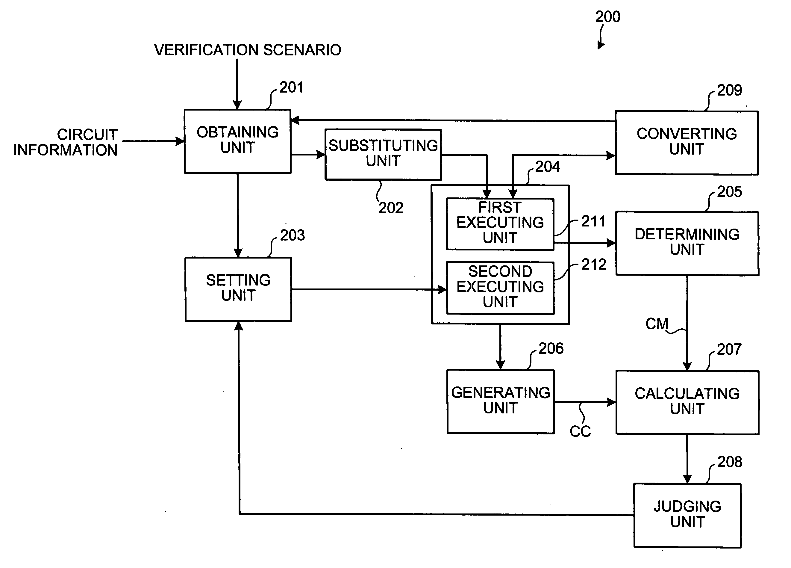
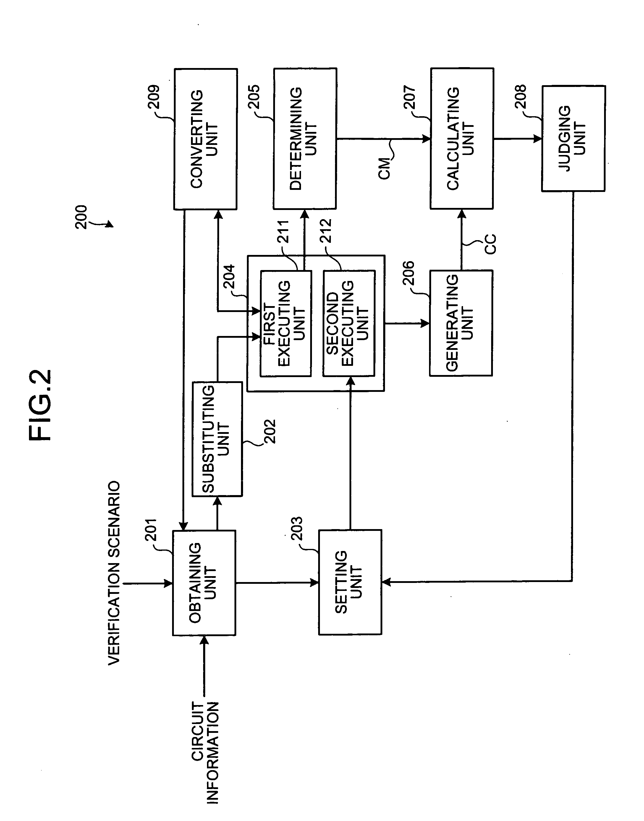
[0181]FIG. 18 is a schematic of a structure of a verification supporting apparatus according to a Components identical to those shown in FIG. 5 are provided with the same reference numerals, and are not described herein.

[0182] While in the first embodiment, the undefined value x is substituted for the variable values (b, c, d, e) of the verification scenario S1 (S2), thereby setting the input pattern PX1 (PX2), in the third embodiment, symbols (p, q, r, s) are substituted for the variable values (b, c, d, e), thereby setting input patterns PX31 and PX32. Then, in a logic simulation, a symbol simulation using the symbols (p, q, r, s) of the input patterns PX31 and PX32 is executed. Thus, logic operation using a symbol for each signal propagation can be performed, thereby obtaining accurate propagation information.

[0183] In the third embodiment, the verification scenarios S1 and S2, the input patterns P1 and P2, and the code coverages CC1 and CC2 used in the first embodiment are als...


PUM


Abstract

In a verification supporting apparatus, when an obtaining unit obtains a verification scenario, a substituting unit substitutes an undefined value for a variable value in the verification scenario. A first executing unit executes a logic simulation using an input pattern. From a result of the logic simulation, a determining unit generates code-coverage upper-limit information. A setting unit sets input patterns by giving an arbitrary logic value to the variable value. A second executing unit executes a logic simulation using the input patterns set. A generating unit generates code coverage from the input patterns set. A calculating unit calculates a level of achievement of the code coverage with respect to the code-coverage upper-limit information.

Description

CROSS-REFERENCE TO RELATED APPLICATIONS [0001] This application is based upon and claims the benefit of priority from the prior Japanese Patent Application No. 2005-003097, filed on Jan. 7, 2005, the entire contents of which are incorporated herein by reference. BACKGROUND OF THE INVENTION [0002] 1) Field of the Invention [0003] The present invention relates to a technology for supporting verification in which a logic design of hardware is verified using a logic simulation. [0004] 2) Description of the Related Art [0005] Conventionally, two major types of verification coverage are used as an index of sufficiency of logic simulation patterns. One of the two types of verification coverage is functional coverage, which is to check whether all functions of a verification target are covered based on external specifications of the verification target. [0006] The other one is code coverage, which is based on a source code of a verification target. The code coverage includes, for example, l...

Claims


Application Information

Patent Timeline
Patent Type & Authority Applications(United States)
IPC IPC(8): G06F17/50
CPCG06F17/5022G06F30/33
Inventor IWASHITA, HIROAKI
Owner FUJITSU LTD
Why Eureka
Try Eureka