Modular microprocessor-based power tool system

a microprocessor and power tool technology, applied in the field of power tools, can solve the problems of many of these tools not being able to optimally use, significant waste of time and raw materials, and inability to optimally use them

Inactive Publication Date: 2006-07-13
HEALTH HERO NETWORK
View PDF99 Cites 166 Cited by
  • Summary
  • Abstract
  • Description
  • Claims
  • Application Information

AI Technical Summary

Problems solved by technology

Although some of these tools are operated by highly skilled craftsman, many of these tools are not.
These individuals often to not have the skills to optimally use their power tools, typically resulting in significant waste of time and raw materials.
Further, even skilled craftsman may have difficulty detecting minor problems with these tools.
Although these tools can provide some feedback as to their operation, they have not been networked or connected in any way to a remotely located expert, professional, or individual capable of providing help to a power tool user.

Method used


Image

  • Modular microprocessor-based power tool system
  • Modular microprocessor-based power tool system
  • Modular microprocessor-based power tool system

Examples


Embodiment Construction

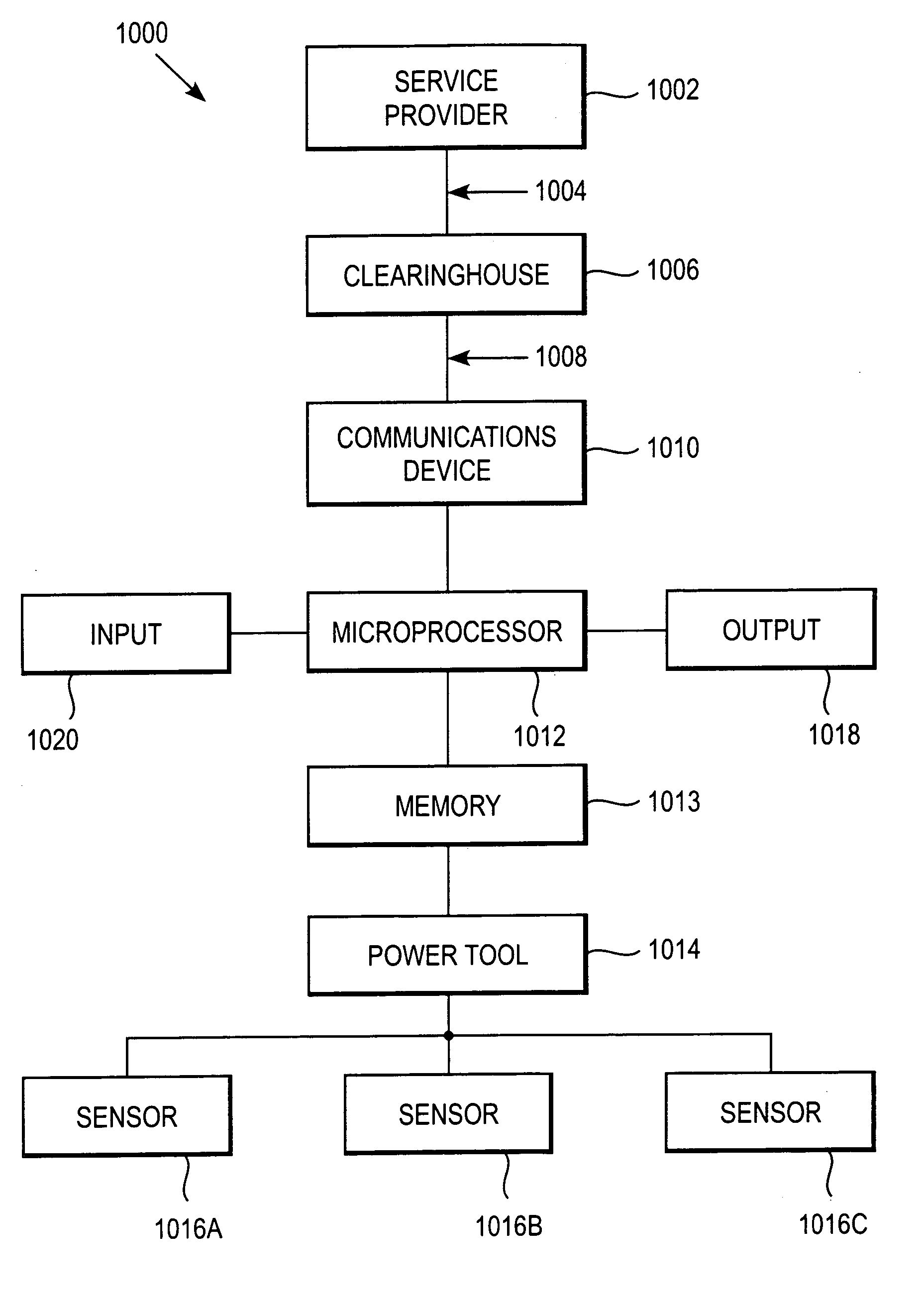
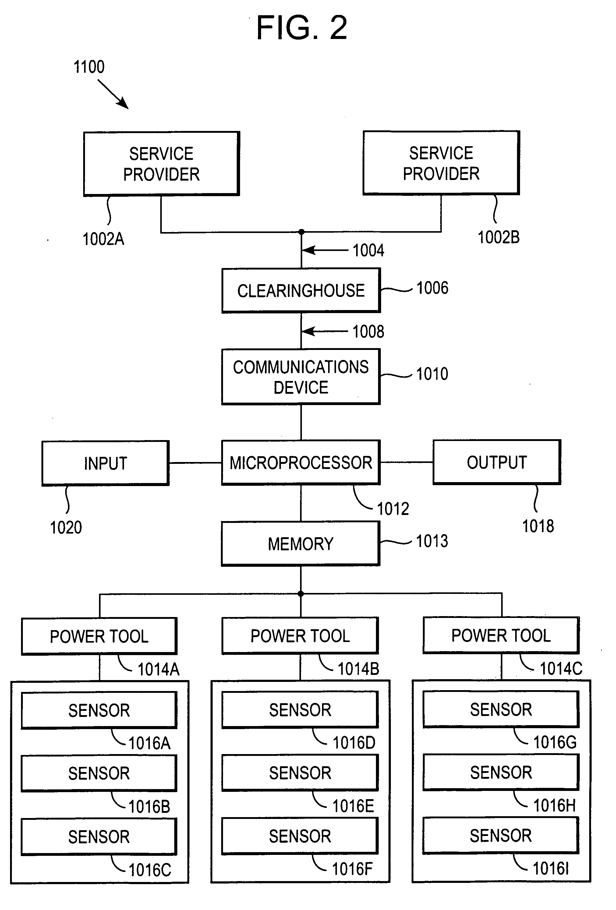
[0032] The present invention, in one embodiment, provides a modular power tool monitoring and management system. Other embodiments of the invention include methods of using power tools employing a modular power tool monitoring and management system. The system may employ a compact microprocessor-based device that includes switches for controlling operation of the unit. The microprocessor-based device processes data supplied by sensors that can be integrated with the power tool to supply signals for displaying relevant information on a display that may be included in the microprocessor-based device or may be integrated into the power tool. The sensors can collect data from the tool and the user's environment and send data to a clearinghouse or central server.

[0033] In one embodiment of the invention, data can be sent from a data management device to a remote clearinghouse having a server and from the server to a remotely located service provider. In this embodiment, the system provi...


PUM

PropertyMeasurementUnit
lengthaaaaaaaaaa
temperatureaaaaaaaaaa
timeaaaaaaaaaa

Abstract

A power tool system and method of using the same is provided. The system can include a programmable microprocessor device including at least one input mechanism, and a memory having instructions and / or other information. The system can also include a display; at least one power tool having at least one sensor operable for monitoring a parameter associated with operation of the power tool. The system can further include a communications device connectable in signal communication with both the programmable microprocessor device and the at least one sensor and program instructions. The method can include the steps of (i) using stored program instructions to generate power tool related information on at least one display and (ii) collecting power tool related data using a programmable microprocessor.

Description

[0001] This application is a continuation-in-part of application Ser. No. 09 / 422,046, filed Oct. 20, 1999, currently pending, which is a continuation of application Ser. No. 09 / 271,217, filed Mar. 17, 1999, now U.S. Pat. No. 6,168,563, which is a continuation-in-part of application Ser. No. 08 / 946,341, filed Oct. 7, 1997, now U.S. Pat. No. 5,997,476. All of the above-identified applications are incorporated herein by reference in their entirety. [0002] The present application is related to U.S. Pat. Nos. 6,168,563; 6,101,478; 5,897,493; 5,307,263; 5,899,855; 6,381,577; 6,248,065; and 6,368,273, which are hereby incorporated by reference in their entirety.BACKGROUND [0003] 1. Field of the Invention [0004] In the following discussion certain articles and methods will be described for background and introductory purposes. Nothing contained herein is to be construed as an “admission” of prior art. Applicant expressly reserves the right to demonstrate, where appropriate, that the article...

Claims


Application Information

Patent Timeline
Patent Type & Authority Applications(United States)
IPC IPC(8): E02F3/96A61B5/00
CPCA61B5/0002Y10T82/30A61B5/087A61B5/14A61B5/14532A61B5/6896A61B2560/0271A61B2560/0431A61B2560/0443A61B2562/0295B25F5/00G06F19/3418G06F19/363G06Q10/06G06Q50/24A61B5/0205G16H10/20
Inventor BROWN, STEPHEN J.
Owner HEALTH HERO NETWORK
Why Eureka
Try Eureka