
Firewall method and apparatus for industrial systems

a technology of industrial systems and firewalls, applied in the field of industrial control systems, can solve problems such as network security problems, and achieve the effect of minimizing processing delays

Active Publication Date: 2006-07-13
ROCKWELL AUTOMATION TECH
View PDF12 Cites 71 Cited by
  • Summary
  • Abstract
  • Description
  • Claims
  • Application Information

AI Technical Summary

Benefits of technology

[0040] In addition, some embodiments include a method for minimizing processing delays when unauthorized communications occur on a system that includes a source device, a target device and a communication stack, the source device sequentially generating and transmitting communication packets for each of the stack communications and, after a packet is transmitted, waiting for a response packet for at least a subset of the communications prior to transmitting another communication packet associated with another of the stack communications, the method comprising the steps of providing a firewall linked to the system, transmitting an original communication packet from the source device that targets the target device, via the firewall intercepting the original communication packet, encapsulating a spoof response packet that simulates a response from the target device and that is of a form that will be accepted by the source device as a legitimate response from the target device, transmitting the spoof response packet to the source device and, via the source, accepting the spoof response packet as a legitimate response packet from the target device and moving on to process the next communication in the stack.

Problems solved by technology

It has been recognized that network security problems can occur when additional routing information is encapsulated or embedded in the data field of an IP data packet that specifies a destination device or resource that is different than the destination device or resource specified in the IP packet frame.

Method used


Image

  • Firewall method and apparatus for industrial systems
  • Firewall method and apparatus for industrial systems
  • Firewall method and apparatus for industrial systems

Examples


Embodiment Construction

[0083] The present invention is now described with reference to the drawings, wherein like reference numerals are used to refer to like elements throughout. In the following description, for purposes of explanation, numerous specific details are set forth in order to provide a thorough understanding of the present invention. It may be evident, however, that the present invention may be practiced without these specific details. In other instances, well-known structures and devices are shown in block diagram form in order to facilitate describing the present invention.

[0084] As used herein, the term “device,” or “resource” is intended to refer to a computer-related entity, either hardware, a combination of hardware and software, software, or software in execution. For example, a device can be, but is not limited to, a process running on a processor, a processor, an object, an executable, a thread of execution, a program, a microprocessor, a processing unit and / or a computer, and hard...


PUM


Abstract

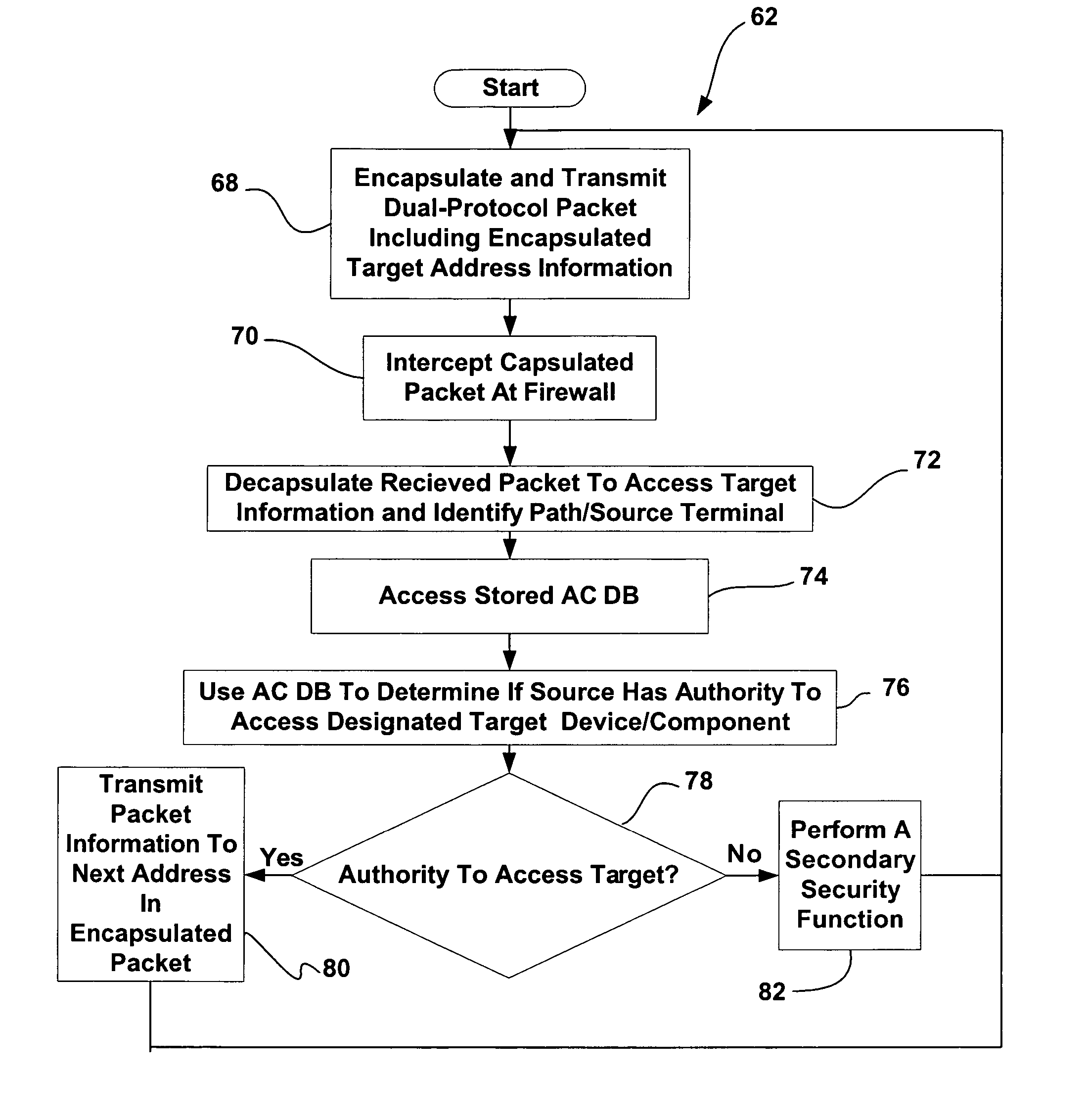
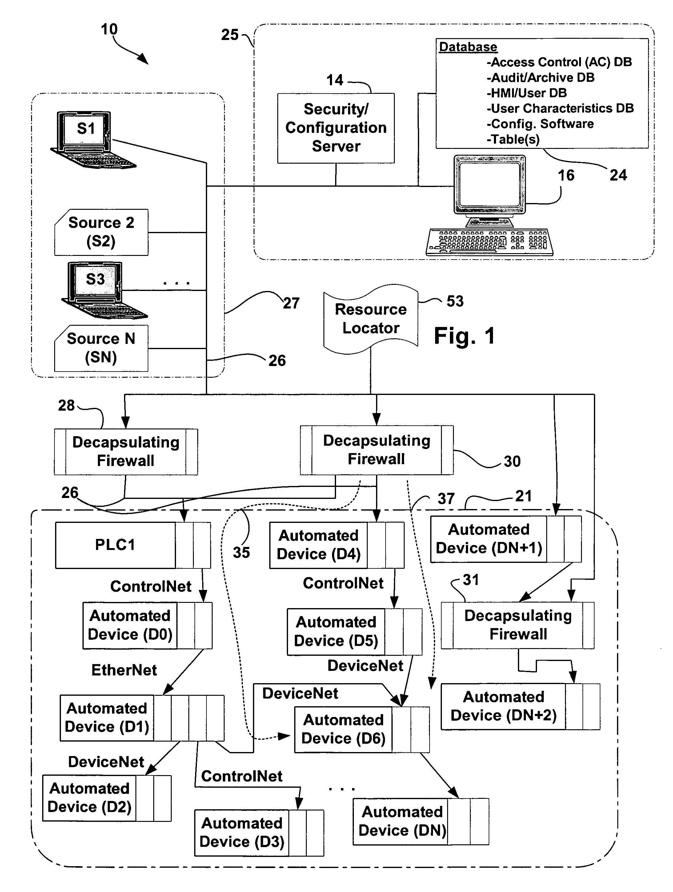
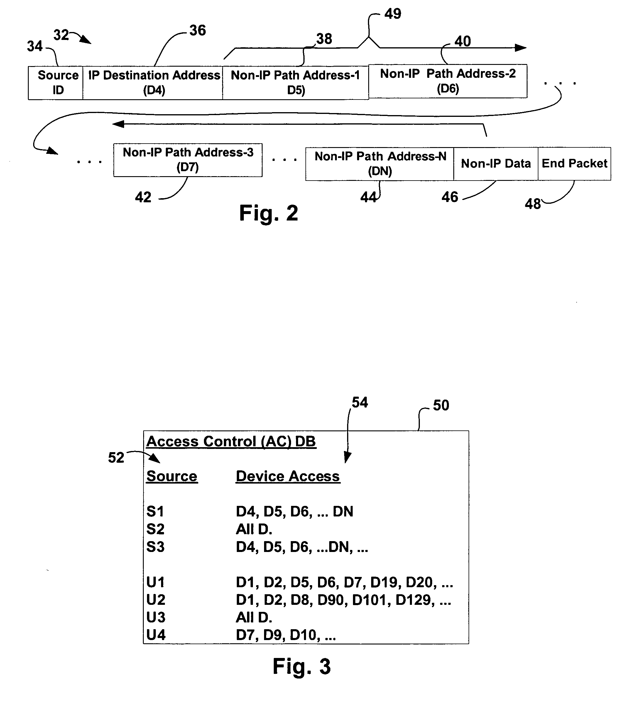
The invention includes a method and apparatus for use with a system including networked resources where communication between resources is via a dual packet protocol wherein a first protocol includes a frame that specifies a destination device / resource and a data field and the second protocol specifies a final destination device / resource and includes a data field and where the second packets are encapsulated in the first protocol packet frames the method including the steps of specifying access control information for resources, for each first protocol packet transmitted on the network, intercepting the first protocol packet prior to the first protocol destination resource, examining at least a subset of the additional embedded packet information to identify at least one of the intermediate path resources and the final destination resource, identifying the access control information associated with the identified at least one of the intermediate path resources and the final destination resource and restricting transmission of the first protocol packet as a function of the identified access control information.

Description

CROSS-REFERENCE TO RELATED APPLICATIONS [0001] This application is related to provisional patent application No. 60 / 641,839 which was filed on Jan. 6, 2005 and which is titled “FIREWALL METHOD AND APPARATUS FOR INDUSTRIAL SYSTEMS” and is also related to provisional patent application No. 60 / 700,380 which was filed on Jul. 19, 2005 and which is also titled “FIREWALL METHOD AND APPARATUS FOR INDUSTRIAL SYSTEMS”.STATEMENT REGARDING FEDERALLY SPONSORED RESEARCH OR DEVELOPMENT [0002] Not applicable. BACKGROUND OF THE INVENTION [0003] The present invention generally relates to industrial control systems, and more particularly to systems and methods that provide secure and firewall restricted Web-based access to control devices and components residing on a non-IP network within an industrial environment. [0004] A typical computer network comprises a plurality of interconnected microprocessor-based devices with specialized (e.g., network) software and / or hardware that facilitates interactio...

Claims


Application Information

Patent Timeline
Patent Type & Authority Applications(United States)
IPC IPC(8): G06F15/16
CPCH04L63/02H04L63/0245H04L69/16H04L69/166H04L69/163H04L63/0263H04L63/10H04L63/0428H04L63/102
Inventor BRANDT, DAVID D.BATKE, BRIAN A.SINGER, BRYAN L.ANDERSON, CRAIG D.SCHULZ, GLENN B.BUSH, MICHAEL A.WILKINSON, JOHN C. JR.PAI, RAMDAS M.SCOTT, STEVEN J.
Owner ROCKWELL AUTOMATION TECH
Learn More