
Data unit sender and method of controlling the same

a data unit and sender technology, applied in the direction of coding, instruments, code conversion, etc., can solve the problem that the data unit sender is not fully using the transmission capacity, and achieve the effect of retransmitting potentially lost data units faster or more aggressively, increasing data throughput, and reducing the number of data units

Active Publication Date: 2006-07-13
TELEFON AB LM ERICSSON (PUBL)
View PDF7 Cites 29 Cited by
  • Summary
  • Abstract
  • Description
  • Claims
  • Application Information

AI Technical Summary

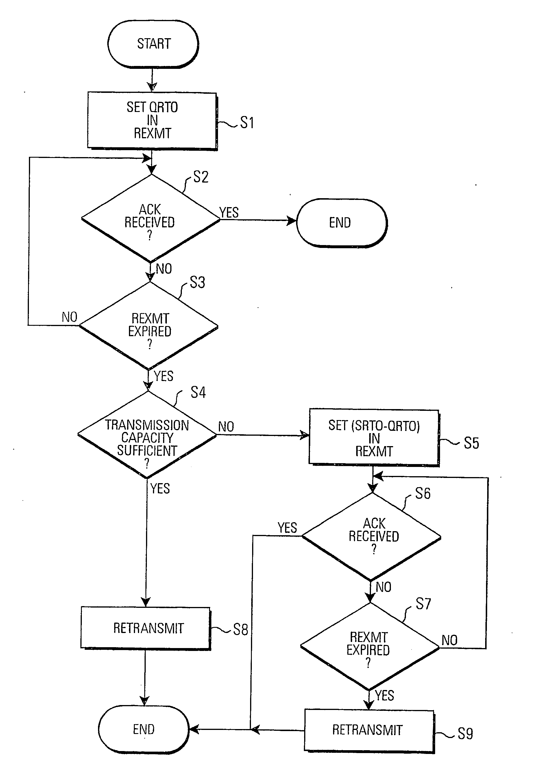
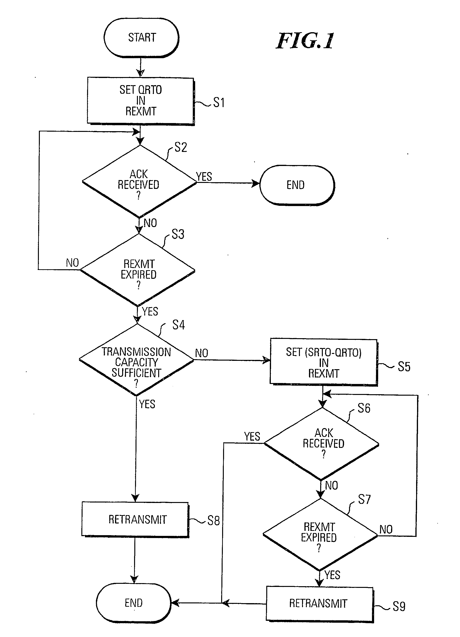
Benefits of technology

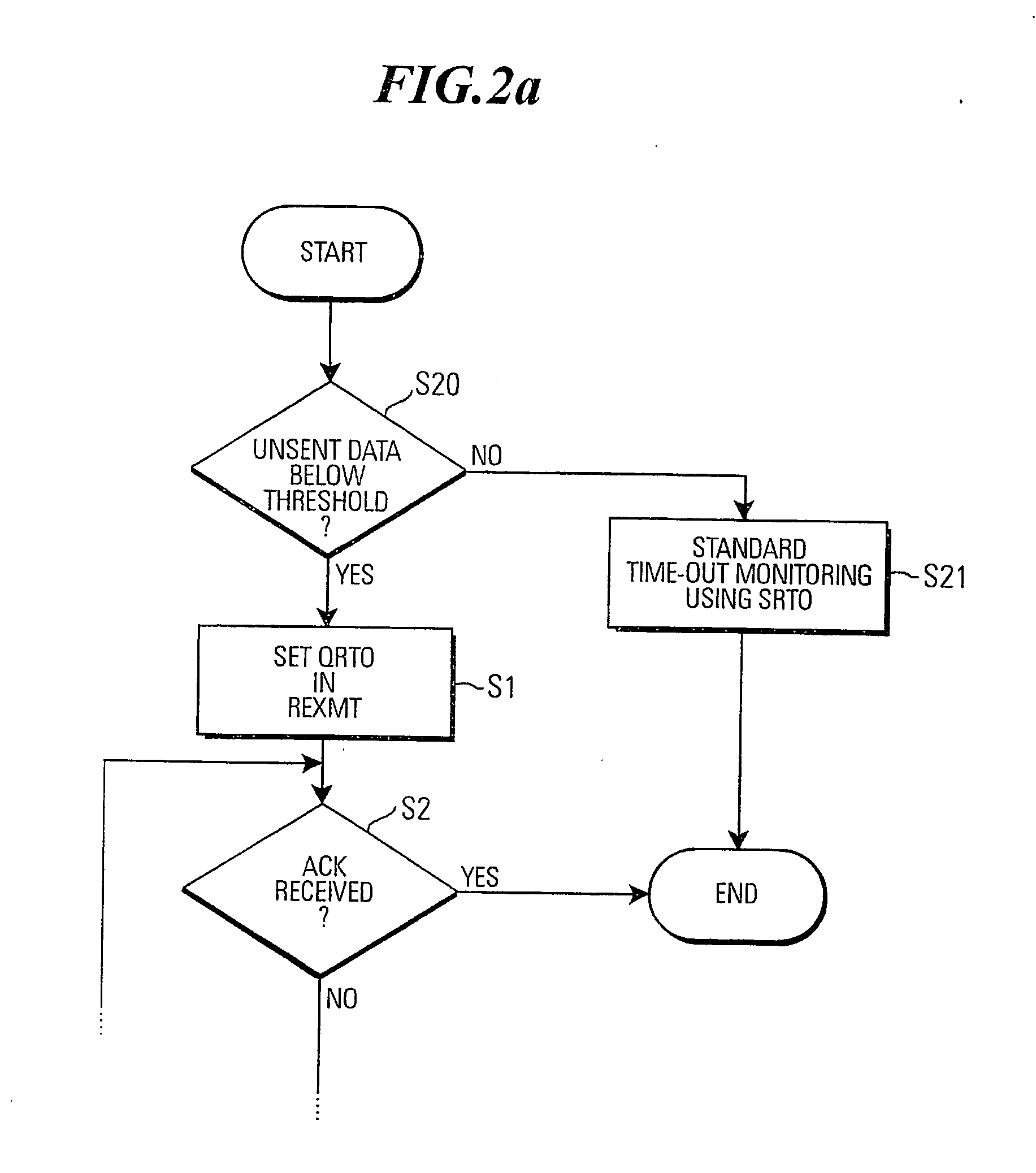
[0012] In this way, the present invention proposes to implement a short time-out period and a long time-out period, where a retransmission occurs after expiration of the short time-out period if the fair share of load on the part of the data unit sender is not exceeded, i.e., if permitted by the above mentioned “available transmission capacity value”. Expressed differently, if the sender is not fully utilizing its transmission capacity for sending yet unsent data, it should be allowed to use this available capacity in any desired way, especially to also retransmit a designated data unit. Thereby, a faster or more aggressive time-out function can be implemented without overloading the network into which the data units are sent.
[0013] There can be many reasons why a data unit sender is not fully using its available transmission capacity. For example, this can be due to the fact that the data unit sender is not receiving more data from a higher layer, e.g. from an application that generates data for the data unit sender to transmit. This can e.g. be the case in interactive applications, such as Telnet, chat, or WWW-interactions, in which the data unit sender (when using the Internet, the data unit sender can be a TCP sender) only has very few data units outstanding (outstanding data units are sometimes also referred to as data units “in flight”) at any given time, because the sending application does not have more data to send. On the other hand, using the TCP sender as an example, if the send window is large, then the difference between the send window size and the data in outstanding packets is also large, and the data unit sender could send more data at once, if such data were present. In accordance with the present invention, the data unit sender can then implement a more aggressive time-out feature and retransmit potentially lost data units more quickly. This increases the data throughput, without overloading the transmission network, as the transmission capacity available to the data unit sender is sufficient for the retransmission.

Problems solved by technology

There can be many reasons why a data unit sender is not fully using its available transmission capacity.

Method used


Image

  • Data unit sender and method of controlling the same
  • Data unit sender and method of controlling the same
  • Data unit sender and method of controlling the same

Examples


Embodiment Construction

[0023] In the following, detailed embodiments of the present invention will be described. It is noted that this description of detailed embodiments serves to provide the skilled person with a better understanding of the invention, but is not intended to be limiting for the invention. The invention is defined by the appended claims. Also, in the course of describing embodiments, reference will sometimes be made to window-based flow control, and more specifically to the transmission control protocol TCP as a preferred example. However, it should be noted that the present invention is by no means restricted to window based flow control or TCP. Much rather, the present invention is applicable in the context of any data unit sender having a limited available transmission capacity value and implementing a time-out monitoring procedure. In this way, the invention can e.g. also be applied to rate based flow control, such as the TFRC protocol.

[0024]FIG. 1 shows a flow chart of a first embod...


PUM


Abstract

A data unit sender and method of controlling a data unit sender are presented, in which a time-out monitoring procedure implements a first, longer time-out period (SRTO), and a second, shorter time-out period (QRTO), where a retransmission is executed after the shorter time-out period if the available transmission capacity value for unsent data is greater or equal to the size of a designated data unit that is to be retransmitted as a result of said time-out monitoring procedure.

Description

FIELD OF THE INVENTION [0001] The present invention relates to a data unit sender and a method of controlling a data unit sender, said data unit sender being arranged to operate in accordance with a communication protocol that provides for a feedback function according to which the sender receives feedback messages that report on the receipt of data units at the receiver of the data unit communication. Examples of such feedback messages are explicit congestion notifications (ECN) originating in the network carrying the data communication, acknowledgment messages originating at the receiver of the data communication, which acknowledge the correct receipt of a transmitted data unit, or non-acknowledgment messages that inform of the non-receipt of sent data units. BACKGROUND OF THE INVENTION [0002] The present invention generally relates to the field of data unit communication. Data unit communication means that an amount of data to be transmitted is divided into individual units, whic...

Claims


Application Information

Patent Timeline
Patent Type & Authority Applications(United States)
IPC IPC(8): H04L1/18
CPCH04L1/1874H04L1/188
Inventor MEYER, MICHAELLUDWIG, REINEREKSTROM, HANNES
Owner TELEFON AB LM ERICSSON (PUBL)
Learn More