Block for constructions, panel for construction using the block, and method of forming panel for construction

a construction block and construction method technology, applied in the field of flat structure construction blocks, can solve the problems of requiring highly-skilled experts in each field, affecting the construction efficiency so as to improve the durability of the flat structure, shorten the time and facilitate the construction process, and increase the strength after the construction of the flat structure.

Inactive Publication Date: 2006-07-20
TAMA HOME
View PDF12 Cites 6 Cited by
  • Summary
  • Abstract
  • Description
  • Claims
  • Application Information

AI Technical Summary

Benefits of technology

[0030] (1) In a block for construction capable of constructing a flat structure by arranging a plurality of the blocks with their outer peripheral surfaces brought into contact with each other, provided are a plurality of through holes formed for inserting linear or bar-like stretching members and recessed parts formed on outer peripheral surfaces crossing the axial direction of the through holes to dispose, in a direction three-dimensionally crossing the stretching members, other stretching members. Therefore, by simply arranging these blocks for structure in a flat state and connecting them, a flat structure such as a wall or a floor of a building can be constructed in a relatively short time and an easy manner while enhancing the durability of the flat structure.
[0031] (2) A plurality of through holes is provided in parallel with each other with intervals therebetween in a through-thickness direction of a body of the block or a direction vertical thereto. As this enables the block body to be firmly held with the stretching members inserted into these through holes, the strength after construction of the flat structure is further increased.
[0032] (3) Cavities opening at more than one place provided on the above-described outer peripheral surfaces can decrease the weight of the block body itself and render heat insulation. In addition, when arranging the plurality of blocks for structure to form a flat structure, these cavities can communicate with each other in a direction along the surfaces so that the weight of the flat structure can be decreased while improving the heat insulation thereof.
[0033] (4) A panel for construction is formed by arranging the blocks for construction as described in the above (1) to (3) in a flat state with outer peripheral surfaces thereof brought into contact with each other and with the plurality of through holes being communicated, inserting the stretching members into the plurality of through holes while disposing the stretching members on the recessed parts, and bonding the blocks for construction by pressure by generating tensile force on these stretching members. By this structure, a flat structure such as a wall or a floor of a building can be easily constructed in a relatively short time. No adhesive agent is used at all, and thus the durability of the flat structure is also improved.
[0034] (5) By attaching reaction force members for generating tensile force on the above stretching members to outer peripheral surfaces of the blocks for construction, which are located on peripheral portions, the strength and the durability can be further improved.
[0035] (6) With a gap filling agent intervening between the adjacent blocks of construction for dispersing reacting force, gaps between the adjacent blocks for construction are filled with the gap filling agent, and the compressive stress generated between the blocks for construction is uniformly dispersed and transmitted over the adjacent blocks for construction. Therefore, generation of cracks or ruptures on the blocks for construction due to concentration of the compressive stress can be prevented.

Problems solved by technology

In the above on-site casting method, however, it takes considerable labor and time to assemble a concrete mold, to cast concrete, and to harden and cure the concrete, which hinders effort to shorten work periods.
Furthermore, these steps require highly-skilled expert engineers in each field.
Therefore, if a road leading to a construction site is narrow or a site is small, workability is extremely lowered.

Method used


Image

  • Block for constructions, panel for construction using the block, and method of forming panel for construction
  • Block for constructions, panel for construction using the block, and method of forming panel for construction
  • Block for constructions, panel for construction using the block, and method of forming panel for construction

Examples


Embodiment Construction

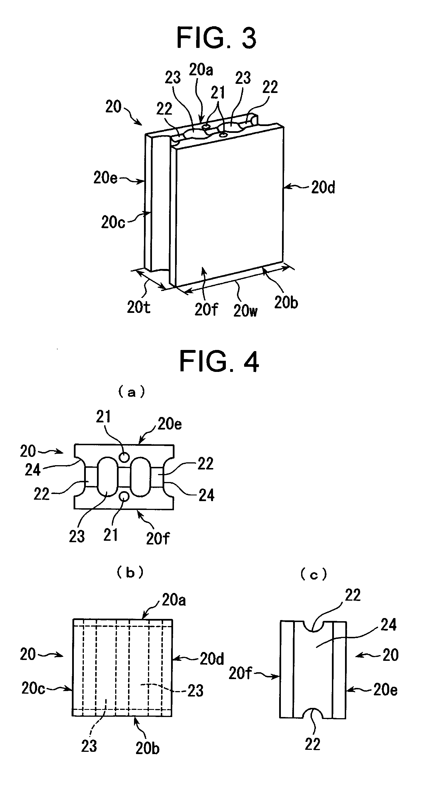
[0088] In reference to FIGS. 1 to 10, explained below are a block for construction and a panel for construction according to first and second embodiments of the present invention.

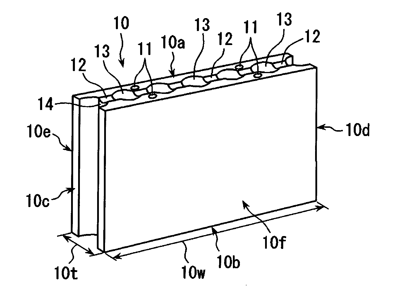
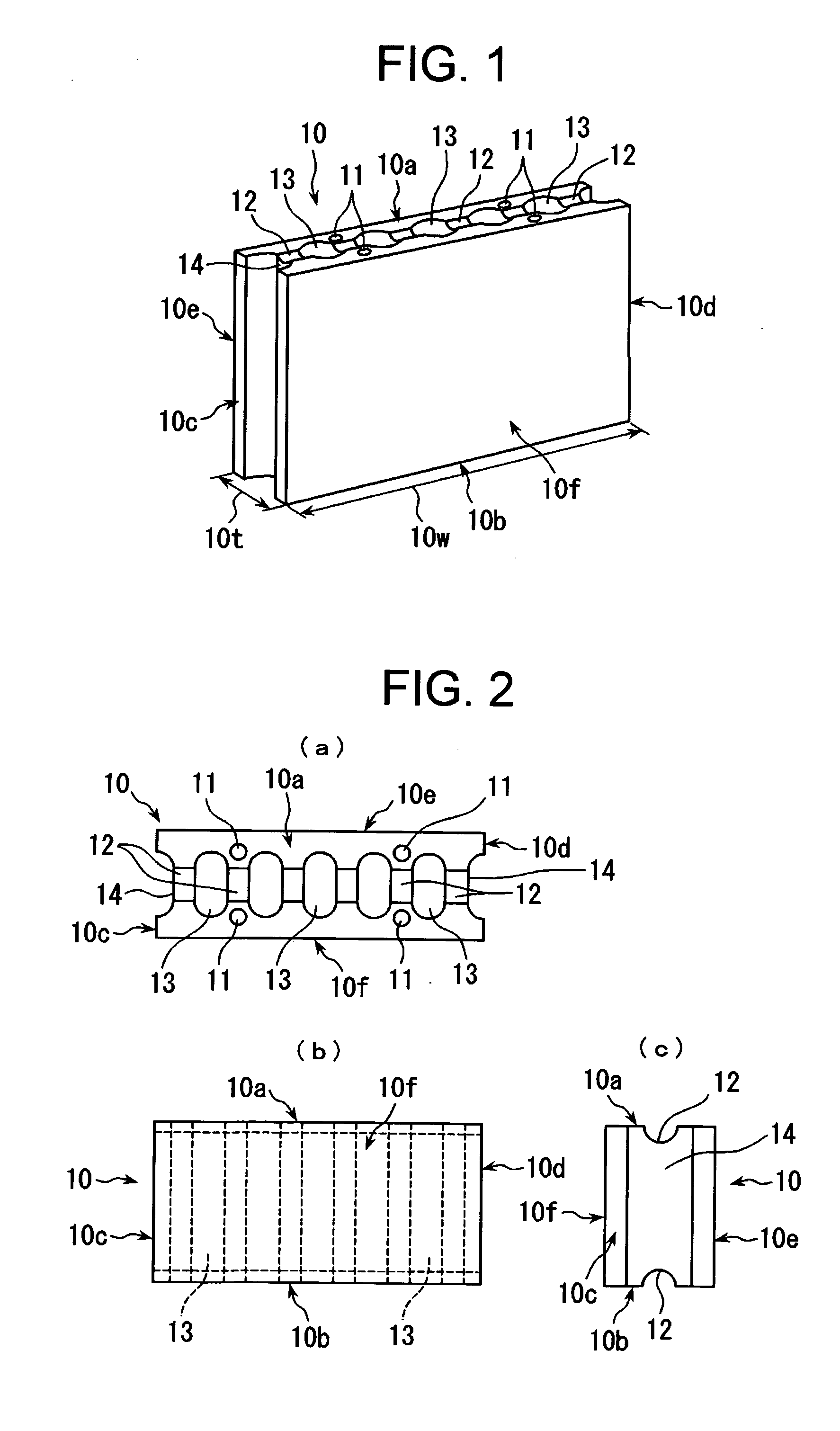
[0089] As shown in FIGS. 1 and 2, a block for construction 10 of the first embodiment of the present invention is, as further described below, a block capable of constructing a flat structure by arranging the plurality of blocks in a flat state with four outer peripheral surfaces thereof, that are, an upper surface 10a, a lower surface 10b, a left side surface 10c and a right side surface 10d brought into contact with each other. In the block for construction 10, a plurality of through holes 11 for inserting bar-like stretching members therein, as further described below, are formed in parallel with a front surface 10f and a rear surface 11e, and recessed parts 12 are formed on the upper surface 10a and the lower surface 10b forming outer peripheral surfaces crossing an axial direction of the through holes...


PUM


Abstract

A block (10) for construction capable of constructing a flat structure by arranging the plurality of blocks in a flat state with four outer peripheral surfaces thereof, that are, an upper surface (10a), a lower surface (10b), a left side surface (10c), and a right side surface (10d) brought into contact with each other. In the block (10) for construction, a plurality of through holes (11) for inserting bar-like stretching members therein are formed parallel with the front surface (10f) and the rear surface (10e) thereof, and recessed parts (12) are formed in the upper surface (10a) and lower surface (10b) forming outer peripheral surfaces crossing the axial direction of the through holes (11) to dispose the other stretching members in a direction three-dimensionally crossing the stretching members inserted into the through holes (11). By using the block (10) for construction, the flat structures such as the wall parts and floor parts of a building can be easily constructed in a rather short period, and the durabilities of these flat structures can also be increased.

Description

TECHNICAL FIELD [0001] The present invention relates to a technique for constructing a flat structure such as a wall, a floor and a ceiling of a reinforced concrete building. BACKGROUND ART [0002] When constructing a structure such as a wall, a floor and a ceiling of a reinforced concrete building, a construction method which has been employed heretofore is that a concrete mold is assembled at a construction site, and reinforcing bars are arranged in the mold, followed by casting of concrete. [0003] In the above on-site casting method, however, it takes considerable labor and time to assemble a concrete mold, to cast concrete, and to harden and cure the concrete, which hinders effort to shorten work periods. Furthermore, these steps require highly-skilled expert engineers in each field. [0004] In addition, a broad work space is needed for carrying in a mold and reinforcing bars to a site as well as for assembling members and casting concrete. Therefore, if a road leading to a constr...

Claims


Application Information

Patent Timeline
Patent Type & Authority Applications(United States)
IPC IPC(8): E04C2/04E04B5/04E04B2/02E04B2/14E04B2/26
CPCE04B2/14E04B2/26E04B5/023E04B5/043E04B2002/0254E04C2/041
Inventor NAKAMURA, MITUO
Owner TAMA HOME
Why Eureka
Try Eureka