Backflow preventer

Inactive Publication Date: 2006-07-20
ALFRED KARCHER GMBH & CO KG
View PDF6 Cites 9 Cited by
  • Summary
  • Abstract
  • Description
  • Claims
  • Application Information

AI Technical Summary

Benefits of technology

[0021] The valve holder is preferably releasably connectable to the second nonreturn valve, for example to its valve housing. This allows assembly of the backflow preventer according to the invention to be additionally simplified.
[0022] To increase the mechanical load-bearing capacity of the backflow preventer, it is advantageous if the first nonreturn valve has a closure body which is

Problems solved by technology

However, in this position an increase in pressure in the region of the outlet opening of the backf

Method used


Image

  • Backflow preventer
  • Backflow preventer
  • Backflow preventer

Examples


Embodiment Construction

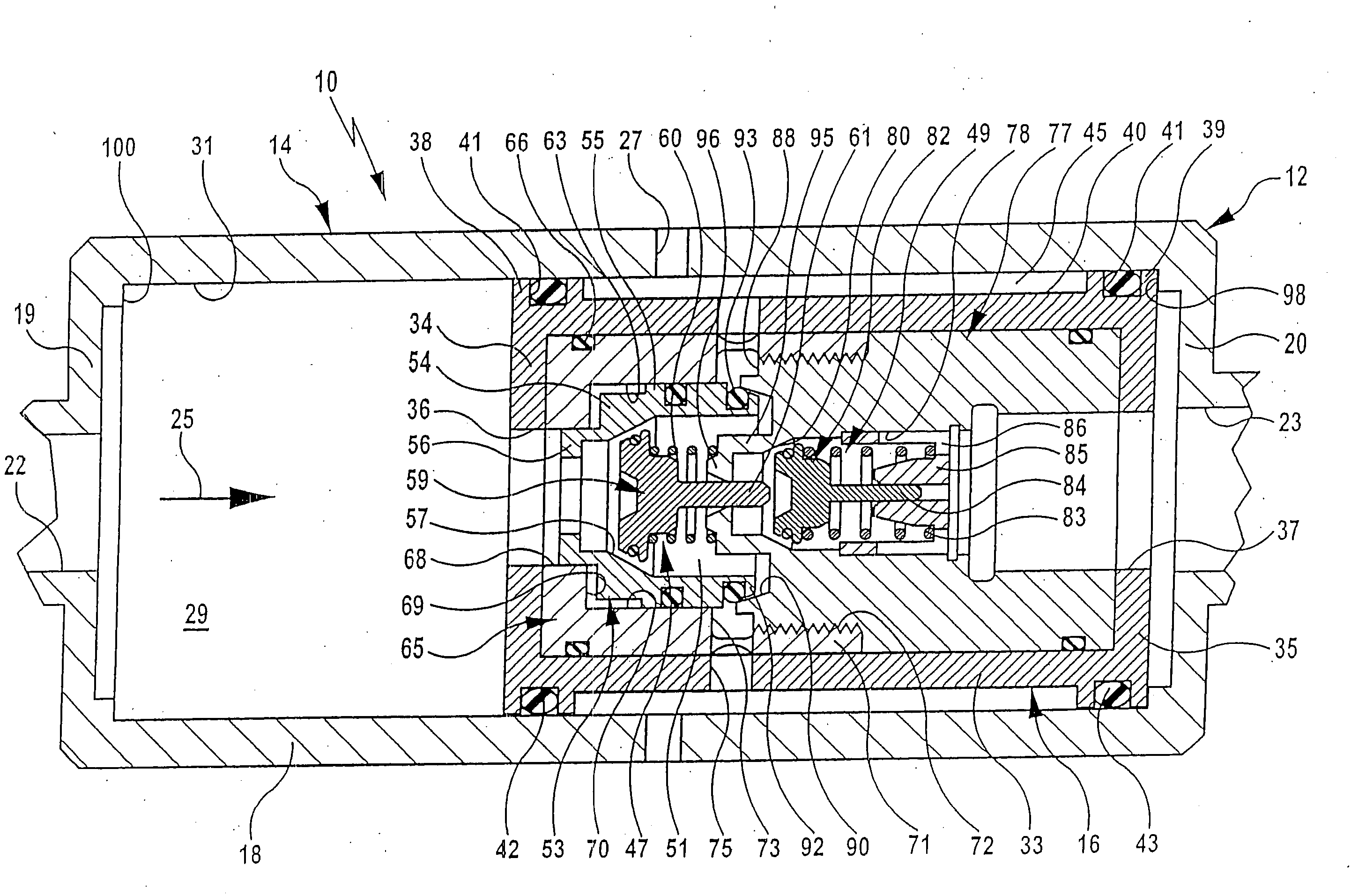
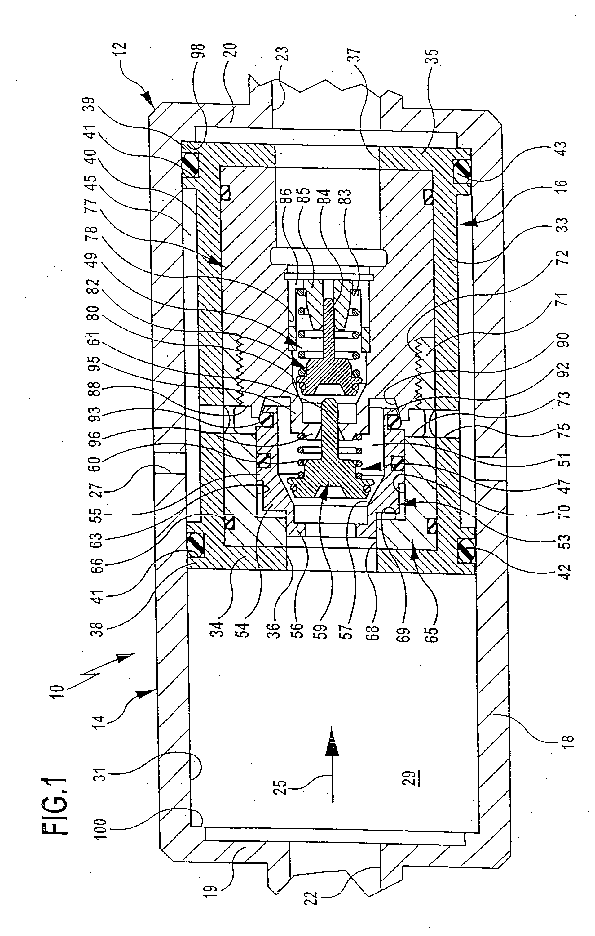
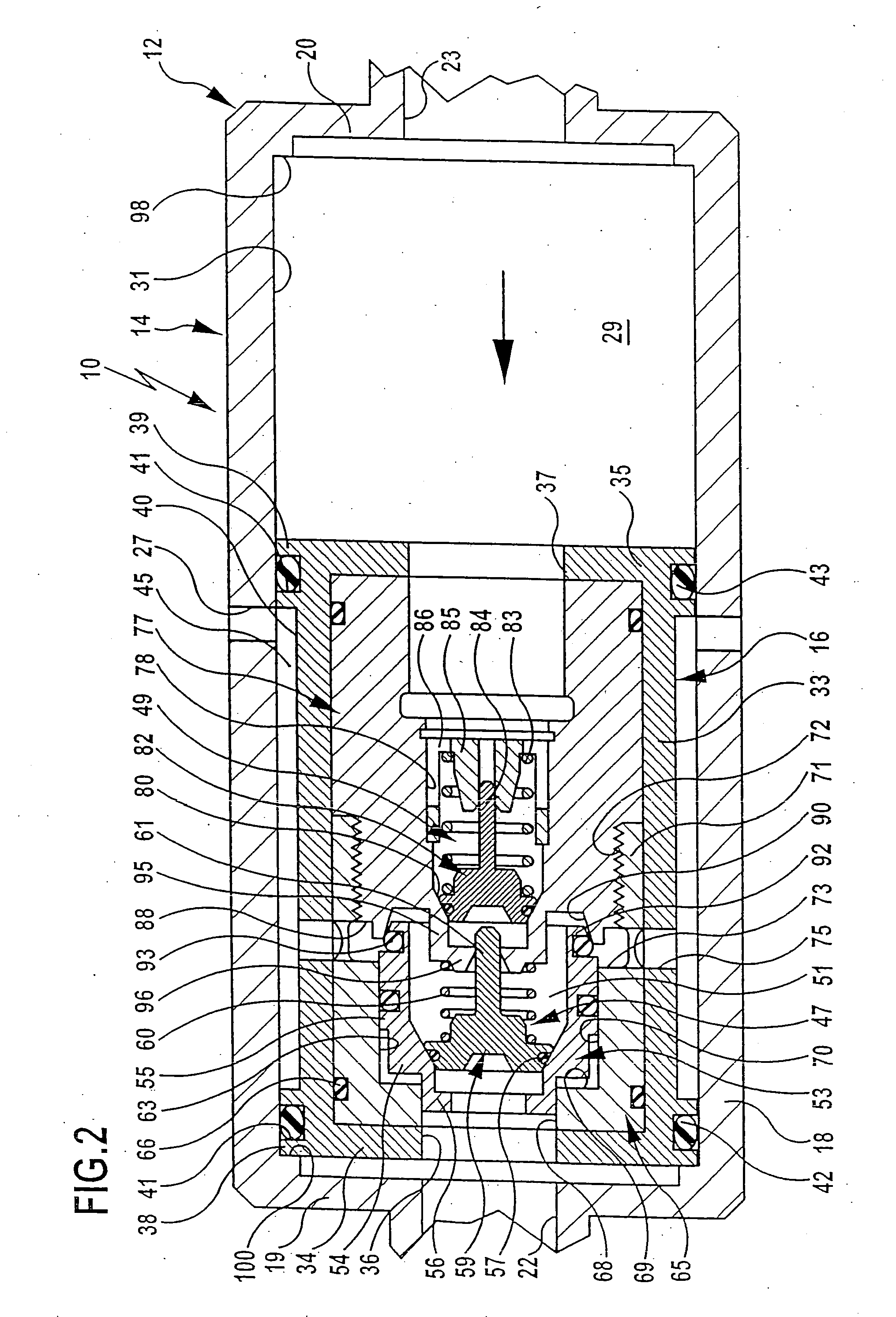
[0028] The drawing illustrates a backflow preventer, which is denoted overall by reference numeral 10 and includes a two-part housing 12 with a hollow-cylindrical outer housing 14 and an inner housing 16 held displaceably within the outer housing 14.

[0029] The outer housing 14 has a housing sleeve 18, which is connected to a housing cover 19 and a housing base 20. An inlet opening 22 is formed in the housing cover 19, and the housing base 20 has an outlet opening 23. At least one and preferably a plurality of leakage openings 27, distributed over the periphery of the housing sleeve 20, have been introduced into the outer housing 14 approximately midway, in the direction of through-flow 25, between the inlet opening 22 and the outlet opening 23.

[0030] The outer housing 14 surrounds an accommodating region 29 in which the inner housing 16 is held such that it can be displaced to and fro in the direction of through-flow 25.

[0031] The inner housing 16 is likewise of hollow-cylindrica...


PUM


Abstract

The invention relates to a backflow preventer having a housing, which has an inlet opening, an outlet opening and at least one leakage opening disposed between these openings and accommodates first and second nonreturn valves disposed in series, the first nonreturn valve being held displaceably in order to open up and close a flow connection between an intermediate space of the housing and the leakage opening. To develop the backflow preventer in such a manner that an inadmissible increase in pressure in the region of the outlet opening can be avoided in a structurally simple way, according to the invention it is proposed that the housing comprises an inner housing and an outer housing, the outer housing having the at least one leakage opening and the inner housing accommodating the two nonreturn valves and being held such that it can be displaced to and fro in the direction of through-flow within the outer housing, and the inner housing having an outlet opening, via which the flow connection between the intermediate space and the leakage opening can be produced independently of the position of the inner housing, by displacement of the first nonreturn valve relative to the second nonreturn valve.

Description

[0001] This application is a continuation of international application number PCT / EP2004 / 008415 filed on Jul. 28, 2004. [0002] The present disclosure relates to the subject matter disclosed in international application number PCT / EP2004 / 008415 of Jul. 28, 2004 and German application number 103 35 380.1 of Jul. 28, 2003, which are incorporated herein by reference in their entirety and for all purposes.BACKGROUND OF THE INVENTION [0003] The invention relates to a backflow preventer, in particular for connecting a high-pressure cleaning appliance to a drinking water supply line, having a housing, which has an inlet opening, an outlet opening and at least one leakage opening disposed between the inlet opening and the outlet opening in the direction of through-flow and which accommodates a first and a second nonreturn valve, which are disposed in series in the direction of through-flow, the first nonreturn valve being held displaceably so as to open up or close a flow connection between ...

Claims


Application Information

Patent Timeline
IPC IPC(8): F16K24/00E03C1/10F16K15/06F16K31/122
CPCE03C1/106F16K15/066F16K31/1226E03C1/108Y10T137/3331
Inventor MUELLER, WOLFGANG
Owner ALFRED KARCHER GMBH & CO KG
Why Eureka
Try Eureka