Soldering iron

a technology of soldering iron and grip, which is applied in the direction of fishing, manufacturing tools, and soldering apparatus, etc., can solve the problems of exposing copper, unable to service the whole soldering iron, and unable to use the soldering tip, so as to increase the friction between the grip and the outer case, and the effect of easy replacemen

Active Publication Date: 2006-07-20
TAIYO ELECTRIC IND
View PDF21 Cites 5 Cited by
  • Summary
  • Abstract
  • Description
  • Claims
  • Application Information

AI Technical Summary

Benefits of technology

[0020] According to this soldering iron, since the outer periphery of the grip is pressed by the inner circumference of the outer case, the frictional force between the grip and the outer case is increased, which serves to more securely fix the soldering tip and the iron body so that it may be preferably used during soldering work.
[0021] According to the soldering iron of the present invention, when replacing the soldering tip of the soldering iron, even when the soldering tip is at a high temperature during soldering work, the soldering tip may be easily replaced without waiting for the soldering tip to cool down.

Problems solved by technology

Nevertheless, iron plating in this type of soldering iron, while not to the extent of copper as mentioned above, still has a property of being leached by melted solder.
Consequently, as soldering work is performed over time with this kind of soldering iron, the iron plating is slowly dissolved into the melted solder, eventually exposing the copper.
Once the copper becomes thus exposed, it is quickly leached away, thereby rendering the soldering tip useless.
That is, repeated soldering degrades the soldering tip, thereby causing the soldering iron as a whole to become unserviceable.
However, when the soldering tip is at a high temperature, the soldering tip cannot be removed by grasping by hand, and so replacement cannot be performed while waiting for the soldering tip to cool down.

Method used


Image

  • Soldering iron
  • Soldering iron
  • Soldering iron

Examples


Embodiment Construction

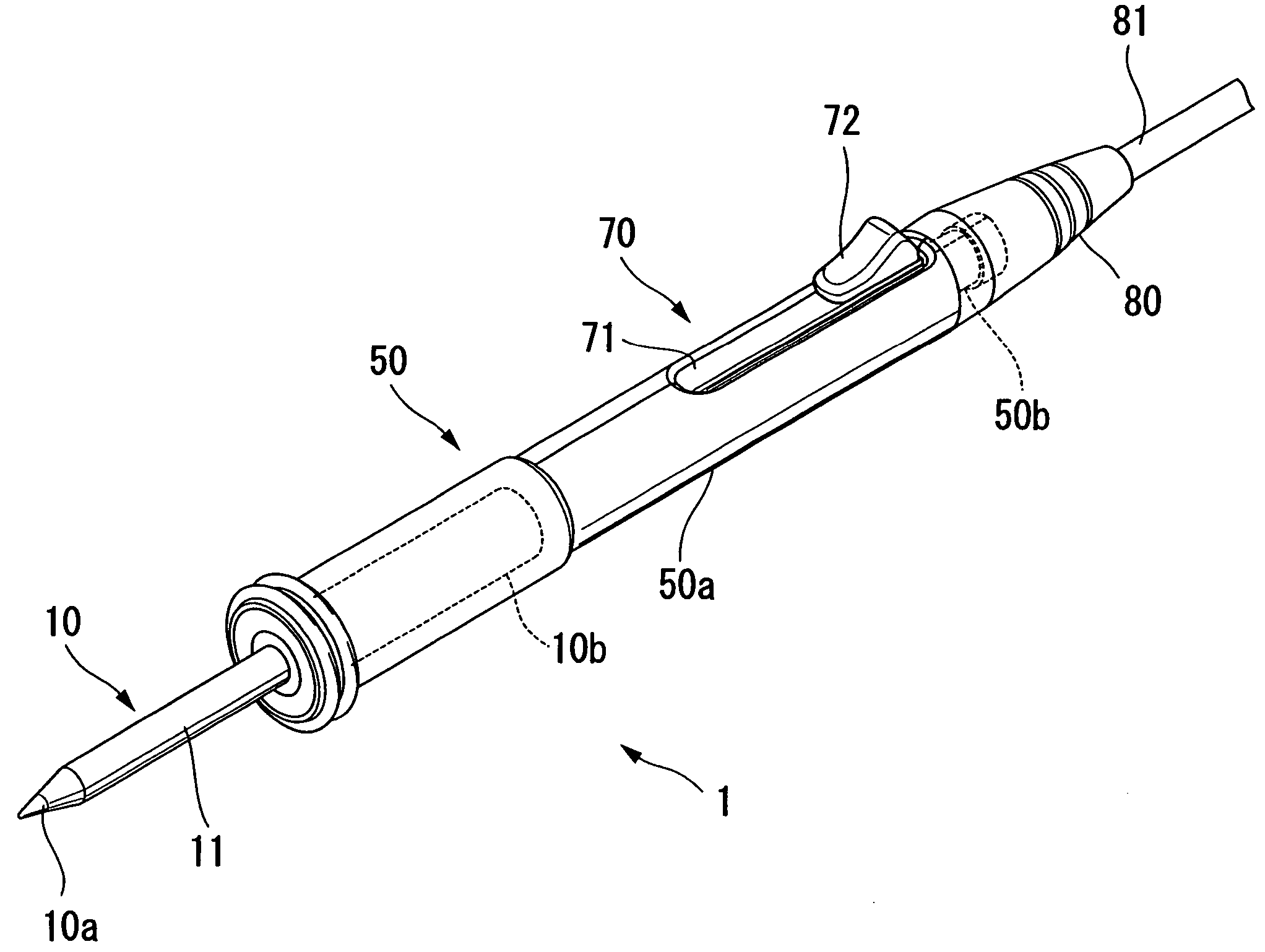
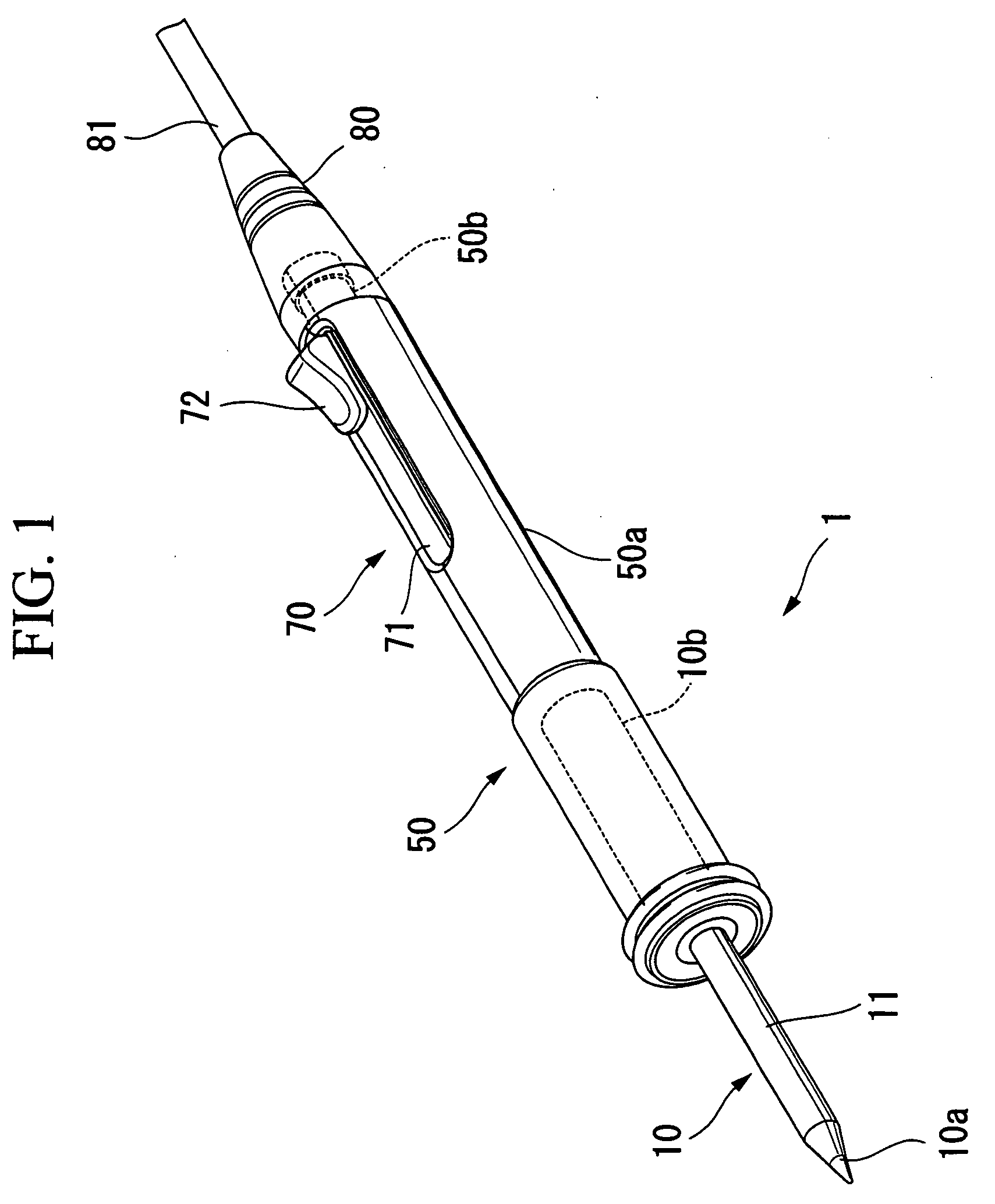
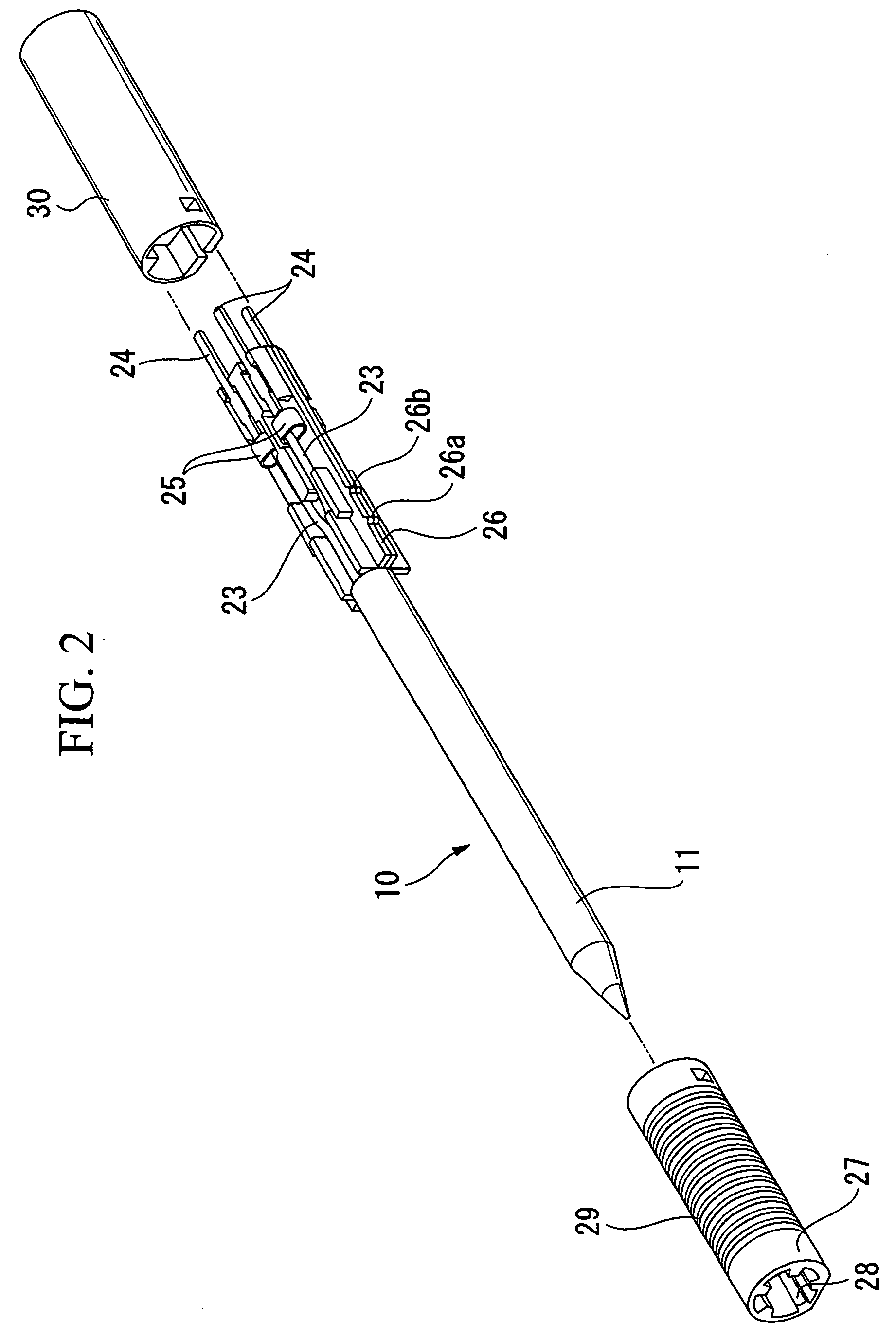
[0033] Below, the preferred embodiment of the soldering iron of the present invention is explained. FIG. 1 is a perspective view of the soldering iron according to the present invention, FIG. 2 is an exploded perspective view of the soldering tip, FIG. 3A is a sectional side elevation of the distal end of the soldering tip, FIG. 3B is an enlarged sectional view of the distal end of the soldering tip, FIG. 4A is a sectional view of the transverse direction of the grip portion, FIG. 4B is a sectional view of the longitudinal direction of the grip portion, FIG. 5 is an exploded perspective view of the soldering iron of FIG. 1, FIG. 6 is an exploded perspective view of the soldering iron of FIG. 1, FIG. 7A is a side view of the state of half of outer case 51 removed from the soldering iron of FIG. 1, and FIG. 7B is an enlarged view of area B shown in FIG. 7A.

[0034] In FIG. 1, reference symbol 1 is the soldering iron of the working example of this embodiment.

[0035] The soldering iron 1...


PUM


Abstract

A soldering iron including: a soldering tip that melts solder at a distal end; an iron body to which the soldering tip is fixed; at least one male connecting end provided at a base end of the soldering tip; at least one female connecting end built into the distal end of the iron body and into which the male connecting end is fittingly inserted; and a grip having heat insulating properties provided around the outer periphery of the soldering tip to cover the base end region of the soldering tip.

Description

BACKGROUND OF THE INVENTION [0001] 1. Field of the Invention [0002] This invention relates to a soldering iron, and particularly to a soldering iron with a replaceable tip. [0003] Priority is claimed on Japanese Patent Application No. 2005-010092, filed Jan. 18, 2005, the content of which is incorporated herein by reference. [0004] 2. Description of Related Art [0005] Soldering tips of soldering irons are widely available having copper of excellent thermal conductivity provided around the heater and the outer surface of the copper being iron plated. The object of iron plating of the soldering tip is to prevent the copper from dissolving into the melted solder, so-called solder leach. The rate of solder leaching of iron plating is approximately one-tenth that of copper. [0006] Nevertheless, iron plating in this type of soldering iron, while not to the extent of copper as mentioned above, still has a property of being leached by melted solder. Consequently, as soldering work is perfor...

Claims


Application Information

Patent Timeline
Patent Type & Authority Applications(United States)
IPC IPC(8): B23K3/02
CPCB23K3/0361A01K91/03
Inventor SHIGEKAWA, TOMOHIRO
Owner TAIYO ELECTRIC IND
Why Eureka
Try Eureka