Multi-positionable rotary vacuum head for product processing

a vacuum head and multi-position technology, applied in the field of automation, can solve the problems of inability to change the tool format, the pick-and-place unit the conventional suction/vacuum design is not easily interchangeable, so as to eliminate the need for adjustment of individual product tooling and ensure repeatability

Inactive Publication Date: 2006-07-20
EASTMAN KODAK CO
View PDF9 Cites 8 Cited by
  • Summary
  • Abstract
  • Description
  • Claims
  • Application Information

AI Technical Summary

Benefits of technology

[0015] A rotational, three position head requires no alignment after changeover due to its positive locating stop mechanism, which provides accurate repeatability regardless of rotational direction.
[0016] Product spacing is fixed and eliminates the need for adjustment of individual product tooling.

Problems solved by technology

In conventional pick-and-place units, it takes hours to convert the pick-and-place unit from one configuration to another.
Conventional suction / vacuum designs were not easily interchanged and tool format changes could not be made.
Operators would do everything possible to avoid changing the machine to a different format, since changing the pick-and-place unit was so inefficient.

Method used


Image

  • Multi-positionable rotary vacuum head for product processing
  • Multi-positionable rotary vacuum head for product processing
  • Multi-positionable rotary vacuum head for product processing

Examples


Embodiment Construction

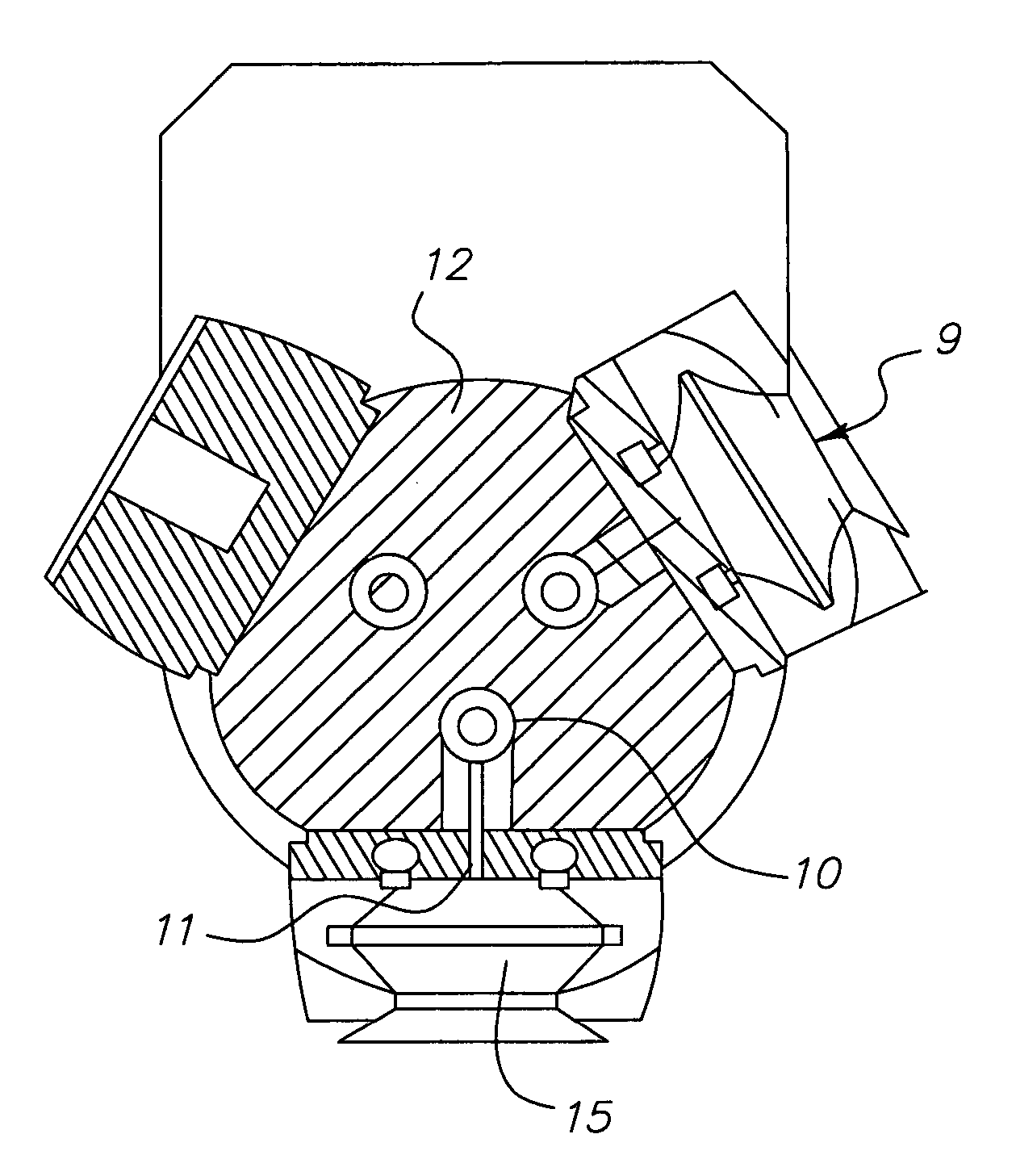
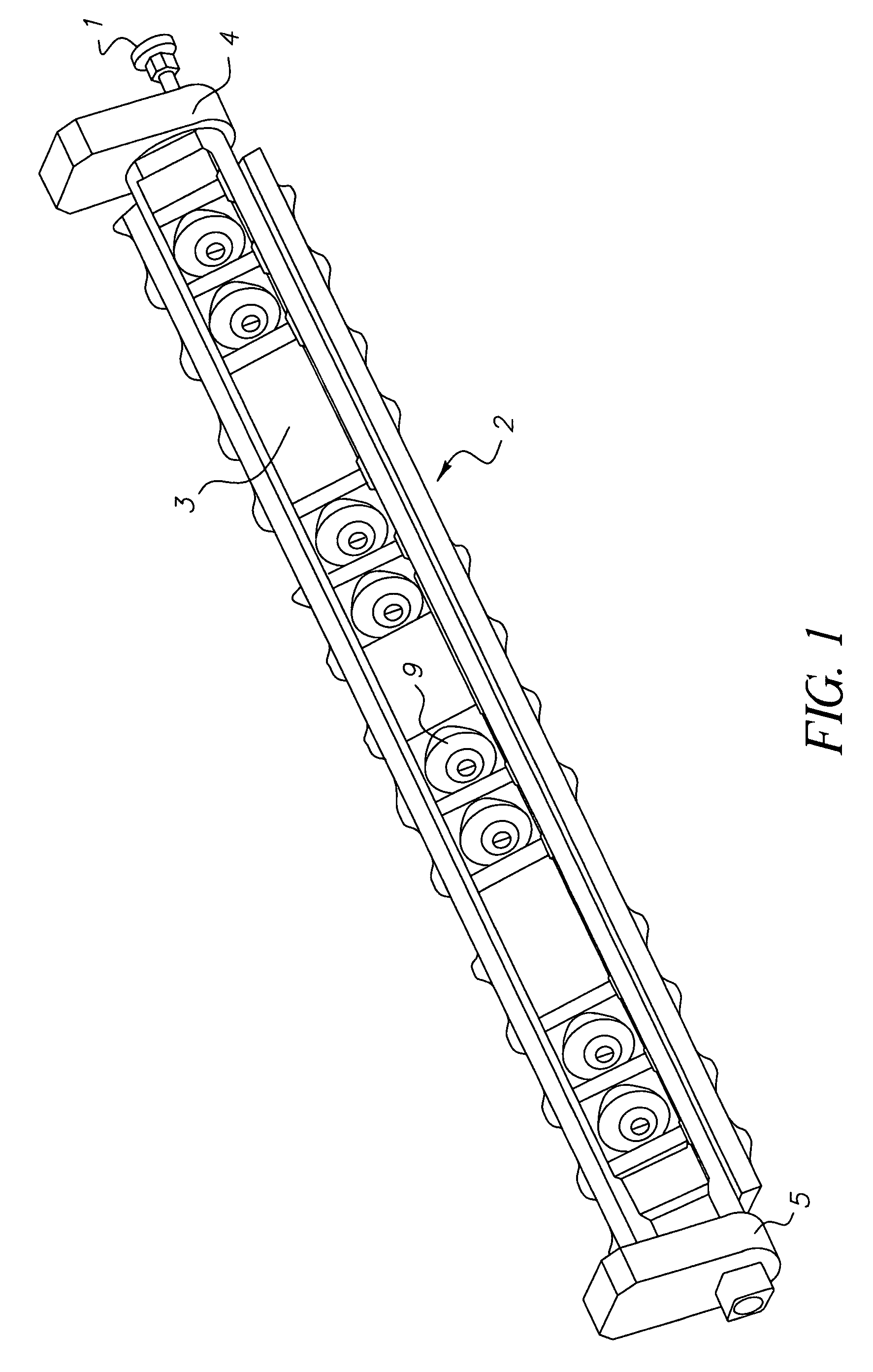
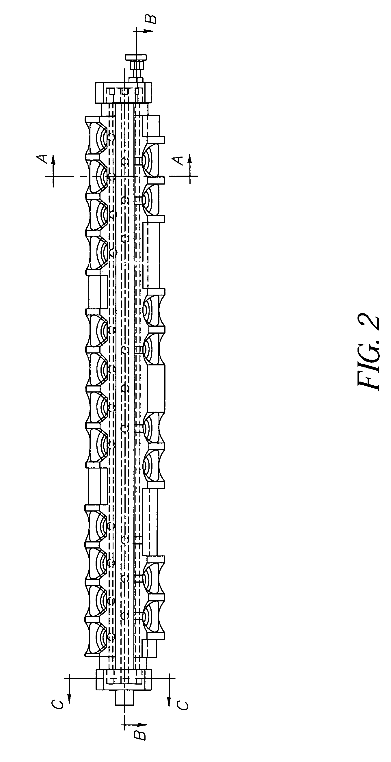
[0025]FIG. 1 is an isometric view of the three-position rotary vacuum head displayed in one of three positions. A rotary head 2 is shown positioned between a locating pin mounting block 4 and a vacuum inlet mounting block 5. In one embodiment, the rotary head 2 may assume three positions and is able to be rotated manually or automatically. The locating pin mounting block 4 is provided to position the assembly shown in FIG. 1 into a larger apparatus and also to receive and coordinate the interaction of a locating pin 1 with the rotary head 2. The locating pin 1 interfaces with the rotary head 2 through the locating pin mounting block 4 to position the rotary head 2 in one of three positions. The vacuum inlet mounting block 5 is provided to position the assembly shown in FIG. 1 into a larger apparatus and also to receive a vacuum to provide a suction force in the rotary head 2.

[0026] The rotary head 2 also includes at least one product locator bar 3 positioned on the circumference of...


PUM


Abstract

An assembly is presented. The assembly includes a rotatable cylinder including product-holding members positioned on the circumference of the cylinder. Several cylinder passageways are deployed within the cylinder, which provides fluid communication between the product holding members and a vacuum. As such, a suction force may be applied from the vacuum through the cylinder passageway to the product-holding member. A locating pin is deployed on one end of the rotating cylinder. The locating pin enables rotation of the cylinder and a positive stop of the cylinder in an aligned position. The locating pin works in conjunction with an O-ring so that vacuum is only applied to one cylinder and one set of product holding members when the locating pin is locked in the positive stop position.

Description

FIELD OF THE INVENTION [0001] The invention relates generally to the field of automation, and in particular to manufacturing automation. More specifically, the invention relates to a pick-and-place unit used for automation on an assembly line. BACKGROUND OF THE INVENTION [0002] The present invention is directed to an assembly for picking up, repositioning, and releasing objects. In the manufacturing industry, these assemblies are often referred to as “pick-and-place” units. The pick-and-place units enable automation of a manufacturing line by enhancing the ability of operators or replacing operators. The pick-and-place units pick up an object enabling a function to be performed on the object or enabling the object to be repositioned. Typically, some type of suction device is integrated into the pick-and-place unit so that when vacuum or suction is applied, the object is held in place by the pick-and-place unit and then the assembly can move the objects. The objects may be anything f...

Claims


Application Information

Patent Timeline
Patent Type & Authority Applications(United States)
IPC IPC(8): B25J15/06
CPCB65B35/38B65G47/918
Inventor MEREDITH, WILLIAM A.HALL, DAVID F.SANFORD, ROBERT W.WEGNER, ROBERT M.
Owner EASTMAN KODAK CO
Why Eureka
Try Eureka