MOS rectifying device, driving method thereof, and motor generator and motor vehicle using thereof

Inactive Publication Date: 2006-07-20
HITACHI LTD
View PDF11 Cites 6 Cited by
  • Summary
  • Abstract
  • Description
  • Claims
  • Application Information

AI Technical Summary

Benefits of technology

[0008] An object of this invention is to provide a MOS rectifying device which can perform rectification normally even when an open phase occurs, a driving method thereof, and a

Problems solved by technology

When an open phase occurs, the conventional control method cannot create turn-off timing and it sometimes happened that

Method used


Image

  • MOS rectifying device, driving method thereof, and motor generator and motor vehicle using thereof
  • MOS rectifying device, driving method thereof, and motor generator and motor vehicle using thereof
  • MOS rectifying device, driving method thereof, and motor generator and motor vehicle using thereof

Examples


Embodiment Construction

[0036] Below will be explained the configuration and operation of a MOS rectifying device which is an embodiment of this invention with reference to FIG. 1 to FIG. 9.

[0037] First will be explained the configuration of the inverter-housed motor generator which uses a MOS rectifying device of the embodiment with reference to FIG. 1.

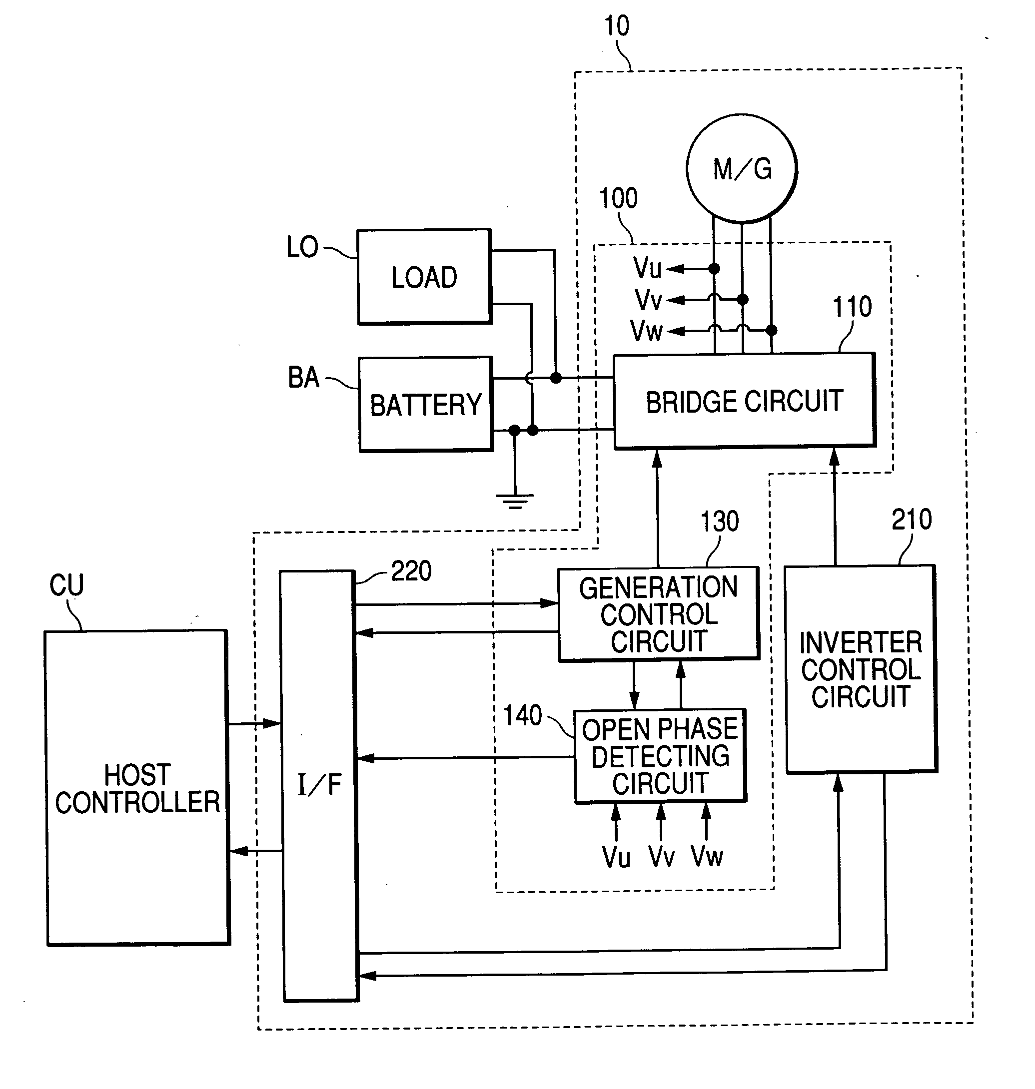
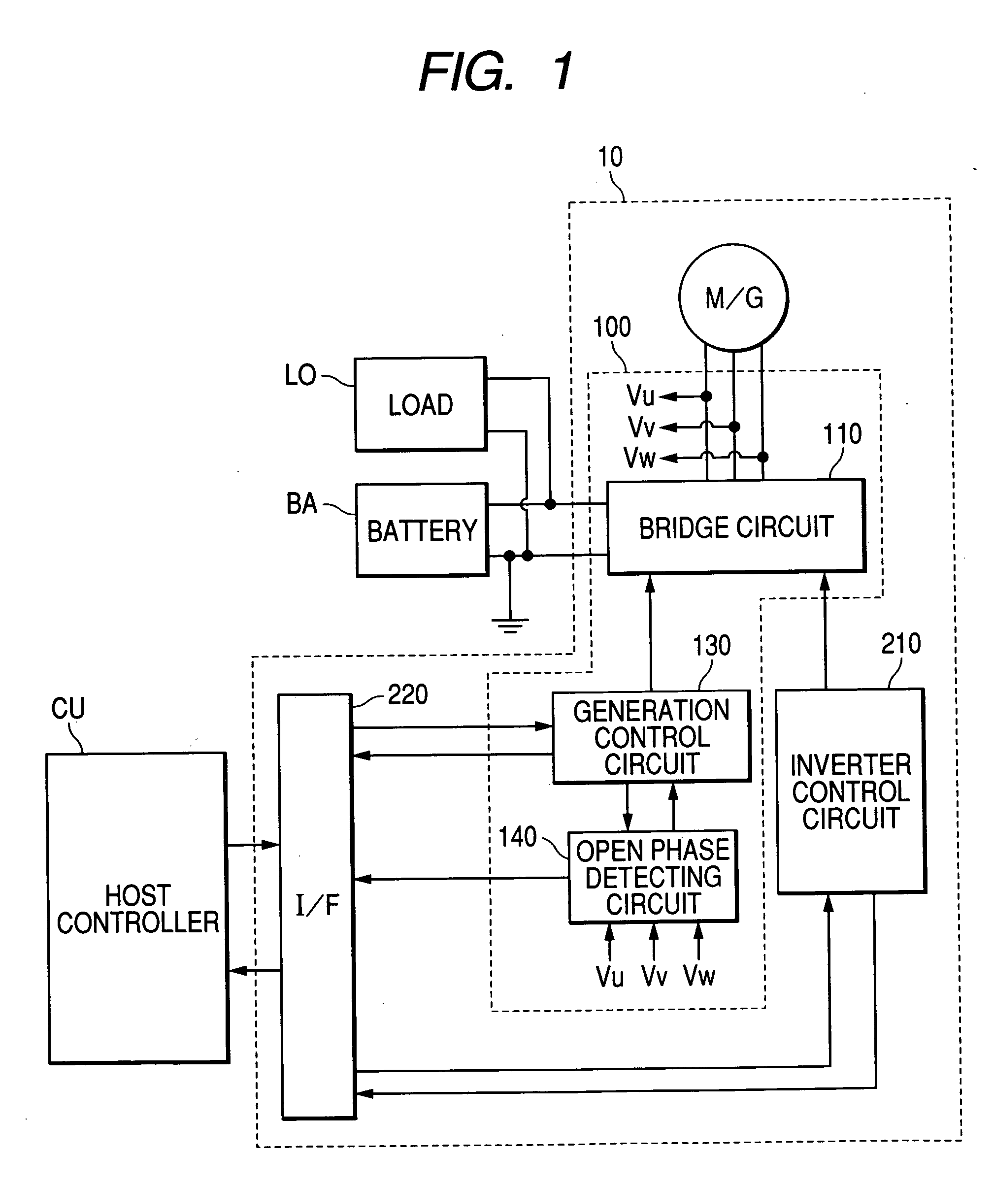
[0038]FIG. 1 shows a functional block diagram of an inverter-housed motor generator using a MOS rectifying device which is an embodiment of this invention.

[0039] Inverter-housed motor generator (M / G) 10 comprises 3-phase motor generator M / G, MOS rectifying device 100 inverter control circuit 210, and interface circuit (I / F) 220. MOS rectifying device 100 receives A.C. voltage from 3-phase motor generator M / G, rectifies the A.C. voltage into a D.C. voltage, and sends it to battery BA which is a secondary battery for storage. The voltage of battery BA is for example, 14V. It is possible to use a 42-V battery instead of the 14-V battery. A required power is...


PUM


Abstract

V-phase upper-arm open phase detecting circuit outputs a permission signal to allow U-phase lower-arm MOSFET to be conductive when the V-phase voltage is higher than the positive electrode potential. In response to this permission signal, U-phase lower-arm driver circuit drives U-phase lower-arm MOSFET. V-phase lower-arm open phase detecting circuit outputs a permission signal to allow U-phase upper-arm MOSFET to be conductive when the V-phase voltage is lower than the negative electrode potential. In response to this permission signal, U-phase upper-arm driver circuit drives U-phase upper-arm MOSFET. Thereby, a MOS rectifying device capable of rectifying even when an open phase occurs, a driving method thereof, and a motor vehicle using thereof can be provided.

Description

CLAIM OF PRIORITY [0001] The present application claims priority from Japanese application serial no. 2005-11643, filed on Jan. 19, 2005, the content of which is hereby incorporated by reference into this application. FIELD OF THE INVENTION [0002] This invention relates to a MOS rectifying device, a driving method thereof, and a motor generator and a motor vehicle using thereof. BACKGROUND OF THE INVENTION [0003] A conventional known MOS rectifying device uses phase voltages to create timing to turn on and off MOS field effect transistors (MOSFETs) which constitute a 3-phase alternating-current generator as disclosed for example by Japanese Patent Laid-Open No. 2003-70256. SUMMARY OF THE INVENTION [0004] When an open phase occurs, the conventional control method cannot create turn-off timing and it sometimes happened that the upper and lower MOSFETs are simultaneously shorted and broken. An open phase means a phase voltage error that occurs [0005] 1) when U, V, and W terminals are o...

Claims


Application Information

Patent Timeline
IPC IPC(8): G05F1/40G05F1/455
CPCH02M7/219H02P2101/45H02P9/30
Inventor INABA, MASAMITSUSHIRAKAWA, SHINJIIWAMURA, MASAHIRO
Owner HITACHI LTD
Why Eureka
Try Eureka