Antiglare film and process for producing the same

a technology of anti-glare film and process, applied in the field of anti-glare film, can solve the problems of deteriorating image visibility, difficult to perceive letters and the like displayed on the screen, and none of the conventional anti-glare films simultaneously satisfy all the above property requirements, and achieve high total light transmittance, high anti-scintillation properties, and high sharpness of transmitted images.

Inactive Publication Date: 2006-07-20
DAI NIPPON PRINTING CO LTD
View PDF13 Cites 23 Cited by
  • Summary
  • Abstract
  • Description
  • Claims
  • Application Information

AI Technical Summary

Benefits of technology

[0010] Accordingly, it is an object of the present invention to provide an antiglare film simultaneously satisfying all of the property requirements, that is, (1) high anti-scintillation properties, (2) high sharpness of transmitted images, (3) high total light transmittance, and (4) high external light reflection preventive properties without significantly altering the form of the conventional antiglare film, that is, the thin film form, and a process for producing the same.
[0020] then drying the coating to reduce the weight ratio of the good solvent to the light-transparent resin, whereby, while allowing the light-transparent fine particles and the light-transparent resin to gel, the coating is solidified to create concaves and covexes on the surface of the coating.

Problems solved by technology

This causes glaring of the display screen or reflection of a fluorescent lamp on the display screen, making it difficult to perceive letters and the like displayed on the screen.
However, when light emitted from the display toward the front is passed, through the antiglare film, shining called “scintillation” occurs on the film surface, disadvantageously posing a problem of deteriorated visibility of displayed images.
None of the conventional antiglare films simultaneously satisfy all the above property requirements.

Method used


Image

  • Antiglare film and process for producing the same
  • Antiglare film and process for producing the same

Examples


example 1

[0084] The following materials were thoroughly mixed together according to the following formulation to prepare a coating composition for a light diffusing resin layer.

Light-transparent resin100pts. wt.Pentaerythritol triacrylate(PET 30, manufactured by Nippon Kayaku Co., Ltd.)Photoinitiator5pts. wt.(Irgacure 184, manufactured by CIBA-GEIGY Ltd.)Light-transparent fine particles8pts. wt.Polystyrene resin filler(particle diameter 1.3 μm, refractive index 1.6)Good solvent60pts. wt.Methyl isobutyl ketone(relative evaporation rate R 1.6)Poor solvent15pts. wt.Isobutyl alcohol(relative evaporation rate R 0.64)

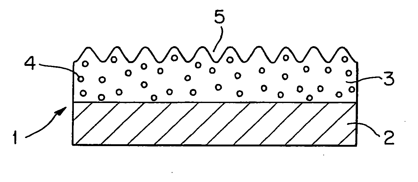
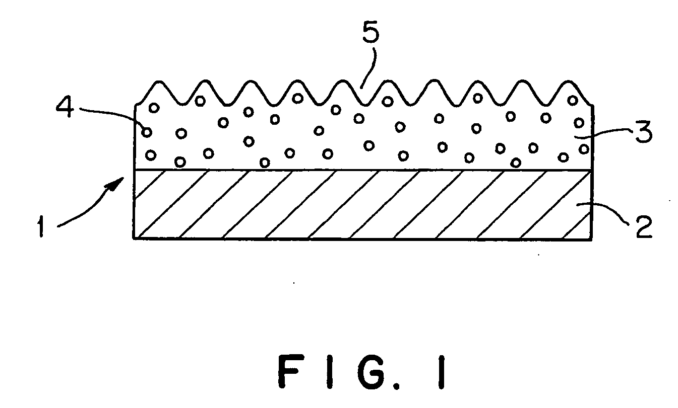
[0085] A cellulose triacetate film (TD-80U, thickness 80 μm, manufactured by Fuji Photo Film Co., Ltd.) was provided as a substrate. The coating composition prepared above was roll coated onto one side of the substrate. The coating was then dried at a temperature of 50° C. to form concaves and convexes on the surface of the coating, followed by application of ultraviolet light at 12...


PUM

PropertyMeasurementUnit
refractive indexaaaaaaaaaa
particle diameteraaaaaaaaaa
temperatureaaaaaaaaaa

Abstract

Disclosed are an antiglare film having a high level of anti-scintillation properties, high sharpness of transmitted images, high light transmittance (total light transmittance), and a high level of external light reflection preventive properties, and a process for producing the antiglare film. A resin and non-agglomerative particles having a specific particle diameter are selected so that the difference in refractive index between the resin and the particles is 0.05 to 0.15. The resin and the non-agglomerative particles are brought to a coating composition using, as a solvent, a good solvent for the resin and a poor solvent for the resin. The coating composition is coated onto a substrate film to form a coating which is then dried. In the course of the drying, as the amount of the good solvent in the coating decreases, the poor solvent acts to cause the gelation of the particles and the resin. Thus, good concaves and convexes can be advantageously formed on the surface of the coating. The layer thus formed can meet various property requirements for antiglare films.

Description

[0001] This is a Continuation of application Ser. No. 10 / 747,227 filed Dec. 30, 2003, which in turn is a Division of U.S. Ser. No. 09 / 576,241 filed May 24, 2000. The entire disclosures of the prior applications are hereby incorporated by reference in their entirety.TECHNICAL FIELD [0002] This invention relates to an antiglare film which, when disposed on the front of CRTs (cathode ray tubes) displays or liquid crystal displays, serves to diffuse light externally incident on these displays, thereby reducing glare. BACKGROUND ART [0003] In CRT displays, accelerated electrons collide with phosphors located on the inner side of the front glass to impart energy to the phosphors. This permits the phosphors to emit light, and, in general, red, green, and blue lights outgo on the front side. In liquid crystal displays, the liquid crystal per se does not emit light. Since, however, light is applied from the backside to enhance the visibility of liquid crystal images, on the whole of the disp...

Claims


Application Information

Patent Timeline
Patent Type & Authority Applications(United States)
IPC IPC(8): B32B5/16C08J7/04C09D7/61C09D7/65C09D161/30G02B1/04G02B5/02
CPCC08J7/04Y10T428/259C09D7/001C09D7/1283C09D7/1291C09D161/30G02B1/111G02B5/0215G02B5/0221G02B5/0231G02B5/0236G02B5/0242G02B5/0268G02B5/0278G02B5/0294H01J2211/44H01J2229/8913H01J2229/8915Y10T428/256Y10T428/2495Y10T428/263Y10T428/24942Y10T428/254Y10T428/24355Y10T428/25C08J2301/12C09D7/20C09D7/69C09D7/70Y10T428/31504C09D7/61C09D7/65G02B1/10
Inventor SUZUKI, HIROKO
Owner DAI NIPPON PRINTING CO LTD
Why Eureka
Try Eureka