Vacuum processing apparatus

a technology of vacuum processing and processing vessel, which is applied in the direction of coating, chemical vapor deposition coating, metallic material coating process, etc., can solve the problems of unstable control temperature, long time for cleaning, and inability to perform high-level processing over the entire surface, so as to achieve rapid reduction of the temperature of the mounting table and the bottom of the processing vessel, the effect of shortening the distance between the mounting table and the processing vessel

Inactive Publication Date: 2006-07-20
TOKYO ELECTRON LTD
View PDF5 Cites 10 Cited by
  • Summary
  • Abstract
  • Description
  • Claims
  • Application Information

AI Technical Summary

Benefits of technology

[0011] The present invention has been made to address the prior art problems discussed above. It is an object of the present invention to provide a vacuum processing apparatus, wherein a temperature detecting unit which detects temperature of a mounting table is protected from corrosion by preventing processing gas from getting into the rear surface side of the mounting table; and in case a power line member is provided for supplying electric power to a resistance heating element, the power line member is also protected from corrosion. The vacuum processing apparatus also allows the distance between the mounting table and the bottom of the processing vessel to be shorter by not having the problem of thermal degradation of a resin sealing member. It is another object of the present invention to provide a vacuum processing apparatus capable of rapidly decreasing the temperature of the mounting table for superior operational efficiency.

Problems solved by technology

As a result, controlling temperature becomes unstable.
Meanwhile, as the size of the wafer 10 becomes increasingly bigger, one of the issues is how to perform processing with high uniformity over the entire surface.
However, this introduces a problem in that it takes a long time to start cleaning after finishing the film forming process.
Otherwise, if the inner pressure of the chamber 1 is raised to speed up the heat transfer rate, it will take a long time to form a vacuum in the film forming apparatus to reach a suitable pressure level for performing cleaning.

Method used


Image

  • Vacuum processing apparatus
  • Vacuum processing apparatus
  • Vacuum processing apparatus

Examples


Embodiment Construction

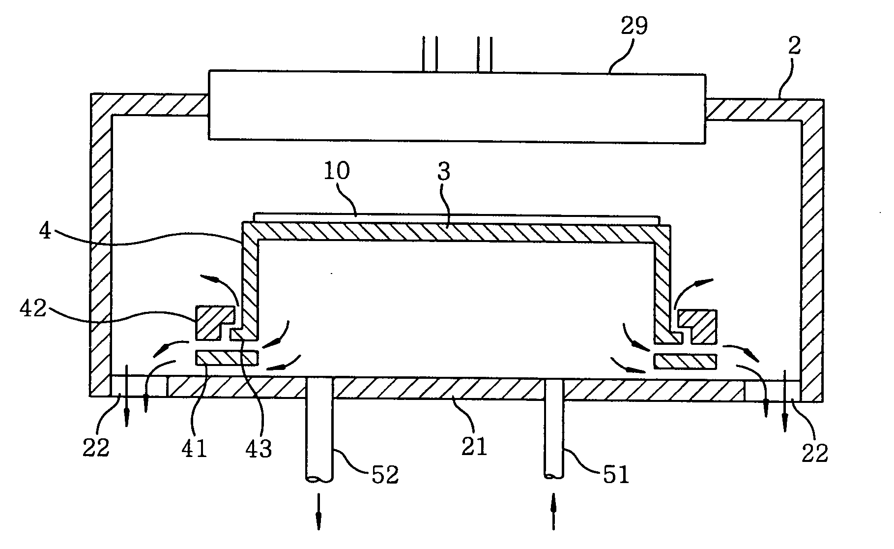
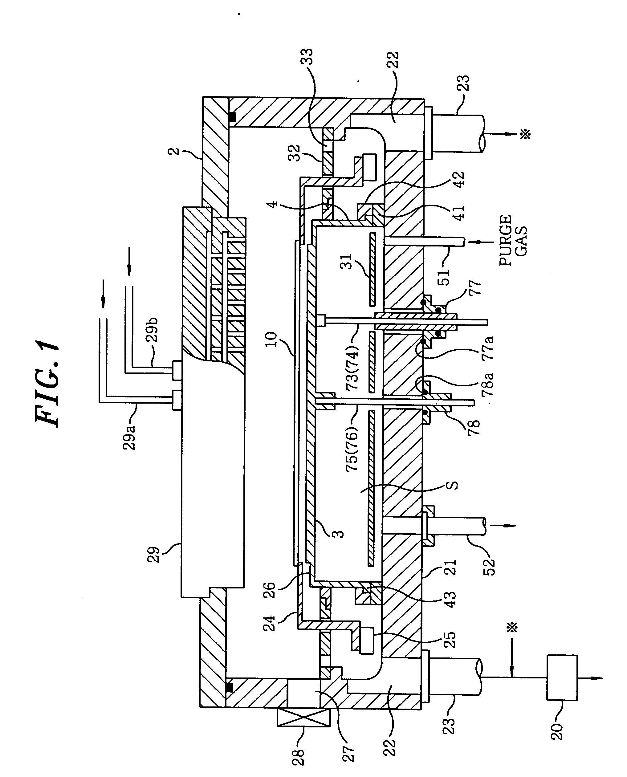
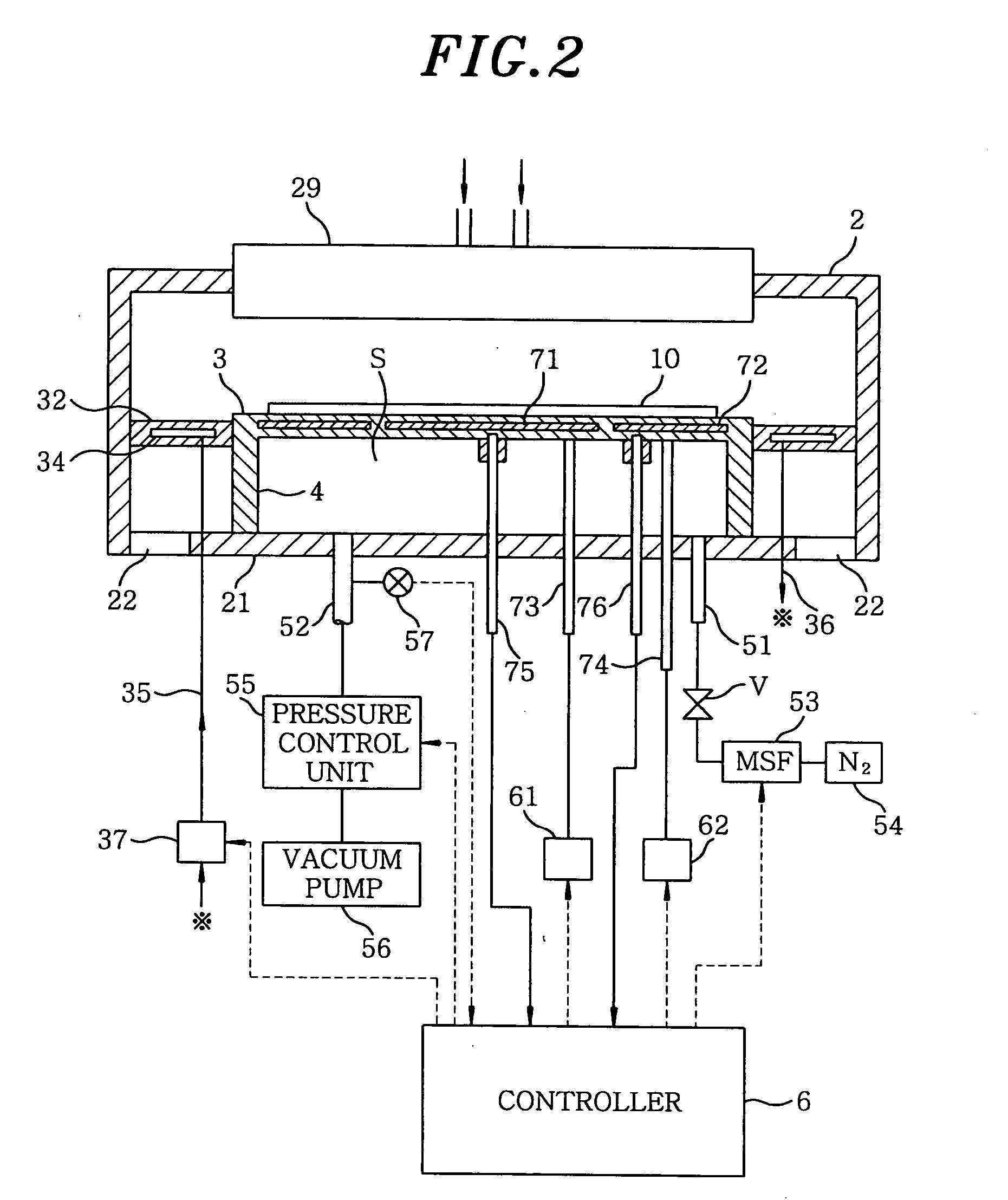
[0029]FIG. 1 shows the entire configuration of a vacuum processing apparatus in accordance with a preferred embodiment of the present invention. The vacuum processing apparatus of the preferable embodiment is, for example, a film forming apparatus for forming a Ti or a TiN film, and has an airtightly sealed cylindrical processing vessel (vacuum chamber) 2. In the processing vessel 2, a mounting table 3 as a substrate supporting unit, is disposed to horizontally support a substrate, e.g., wafer 10. The mounting table 3 is in a circle shape whose size is bigger than wafer 10. A cylindrical part 4 connected to the periphery of the mounting table 3 vertically extends down from its underside. The mounting table 3 and the cylindrical part 4 made of, e.g., a ceramic material such as aluminum nitride (AlN) or alumina (Al2O3), as one unit, make up a cylindrical member, which has an open top portion and a lower end with a bottom.

[0030] Further, a ring-shaped heat insulating material 41, whos...


PUM

PropertyMeasurementUnit
temperatureaaaaaaaaaa
pressureaaaaaaaaaa

Abstract

A vacuum processing apparatus is constituted of the following portions: a processing container with the bottom, capable of drawing vacuum; a placement platform installed in the container; a heating portion for heating a substrate on the platform; a processing gas-feeding portion for feeding a processing gas into the container; a partitioning portion surrounding a space between the platform and the bottom of the container and partitioning off the space from a processing space in the container; a purge gas-feeding portion for feeding a purge gas into the space surrounded by the partitioning portion; a purge gas-discharging portion for discharging the purge gas from the space surrounded by the partitioning portion; a control portion for controlling the purge gas-feeding portion and/or the purge gas-discharging portion so as to regulate the pressure in the space surrounded by the partitioning portion; and a temperature-detecting portion penetrating the bottom of the container, inserted in the space surrounded by the partitioning portion, and having the top end in contact with the platform. The partitioning portion has the lower end in surface-contact with the bottom of the container. The control portion regulates the pressure in the space surrounded by the partitioning portion to a pressure higher than that in the processing space in the container.

Description

FIELD OF THE INVENTION [0001] The present invention relates to a vacuum processing apparatus for carrying out e.g., a film forming process on a substrate in a vacuum atmosphere (depressurized state). BACKGROUND OF THE INVENTION [0002] The manufacturing process of a semiconductor device includes a process of forming wiring by burying a metal or metal compound in holes or grooves formed in a semiconductor wafer (hereinafter, referred to as ‘wafer’) by CVD (chemical vapor deposition). An apparatus for forming a film of a metal or metal compound on a wafer is disclosed, for example, in Japanese Patent Laid-open Application No. 2003-133242 (Japanese Patent Application No. 2001-384649). [0003] The film forming apparatus described in Japanese Patent Laid-open Application No. 2003-133242 is schematically shown in FIG. 7. Reference numeral 1 is a chamber whose upper portion is a flat cylindrical part 1a while the chamber's lower portion is a cylindrical part 1b with a smaller diameter. Insta...

Claims


Application Information

Patent Timeline
Patent Type & Authority Applications(United States)
IPC IPC(8): H01L21/44C23C16/00C23C16/44C23C16/455H01L21/205
CPCC23C16/455C23C16/45521H01L21/68785C23C16/4405C23C16/4586H01L21/67103H01L21/67109H01L21/67248
Inventor KASAI, SHIGERUKATOH, SUSUMUKOMATSU, TOMOHITOSAITO, TETSUYATANAKA, SUMI
Owner TOKYO ELECTRON LTD
Why Eureka
Try Eureka