
Organic light emitting diode display device

a light-emitting diode and display device technology, applied in the direction of measurement devices, instruments, heat measurement, etc., can solve the problems of difficult to predict the influence exerted on the panel by the external environment, excessive temperature increase, etc., to reduce the temperature of the organic light-emitting diode panel, the effect of increasing the lifespan of the oled panel and simplifying the structur

Active Publication Date: 2021-12-23
LG ELECTRONICS INC
View PDF2 Cites 1 Cited by
  • Summary
  • Abstract
  • Description
  • Claims
  • Application Information

AI Technical Summary

Benefits of technology

The patent describes a technology for improving the lifespan of OLED displays by quickly reducing their temperature when they overheat. This is done by changing the current limit value, which allows for real-time temperature adjustments based on the external temperature. This technology eliminates the need for additional temperature sensors and reduces manufacturing costs. Additionally, it improves the reliability of OLED displays by preventing excessive brightness loss and ensuring the temperature of the display matches the external situation.

Problems solved by technology

Meanwhile, when the OLED display device continuously displays an image having the secondary color, a panel temperature may be excessively increased.
In other words, the panel of the OLED display device may have a problem that a temperature is increased depending on an input image.
In addition, since countries have different summer temperatures, and households have different environments (for example, an environment in which an air conditioner to discharge cold air is installed around the OLED display device or an environment in which heat is severely generated around the OLED display device) in which the OLED display device is installed, it may be difficult to predict an influence exerted on the panel by the external environment.

Method used


Image

  • Organic light emitting diode display device
  • Organic light emitting diode display device
  • Organic light emitting diode display device

Examples


Embodiment Construction

]

[0045]Hereinafter, the present disclosure will be described in detail with reference to the drawings.

[0046]The suffixes “module” and “unit” for components used in the description below are assigned or mixed in consideration of easiness in writing the specification and do not have distinctive meanings or roles by themselves.

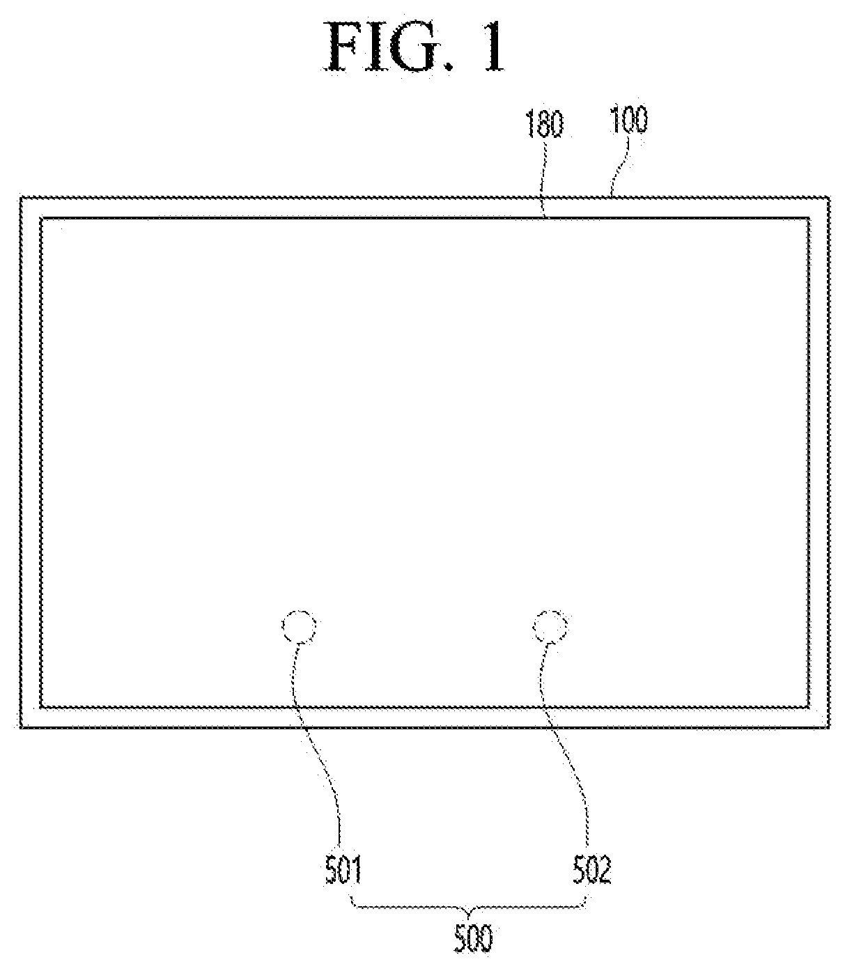
[0047]FIG. 1 is a diagram illustrating an image display apparatus according to an embodiment of the present disclosure.

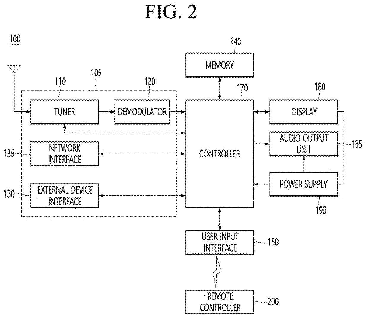
[0048]With reference to the drawings, an image display apparatus 100 includes a display 180.

[0049]On the other hand, the display 180 is realized by one among various panels. For example, the display 180 is one of the following panels: a liquid crystal display panel (LCD panel), an organic light-emitting diode (OLED) panel (OLED panel), and an inorganic light-emitting diode (OLED) panel (OLED panel).

[0050]According to the present disclosure, the display 180 is assumed to include an organic light-emitting diode (OLED) panel (OLED).

[0051]Hereinafter...


PUM

PropertyMeasurementUnit
temperatureaaaaaaaaaa

Abstract

The present invention relates to an organic light emitting diode display device which minimizes a temperature increase of an organic light emitting panel in consideration of an input image and an external environment, the organic light emitting diode display device comprising: an organic light emitting panel; a power supply unit for supplying a current to the organic light emitting panel; a control unit for performing an automatic current limit for controlling the maximum value of the current supplied to the organic light emitting panel to be less than or equal to the current limit value; and a temperature sensor for sensing the temperature of the organic light emitting panel, wherein the control unit may change the current limit value according to the present temperature of the organic light emitting panel.

Description

TECHNICAL FIELD[0001]The present disclosure relates to an organic light emitting diode display device, and more particularly, to an organic light emitting diode display device capable of minimizing a temperature increase of an organic light emitting diode panel.BACKGROUND ART[0002]In recent years, the types of display devices have been diversified. Among them, an organic light emitting diode (OLED) display device is widely used.[0003]Since the OLED display device is a self-luminous device, the OLED display device has lower power consumption and can be made thinner than a liquid crystal display (LCD) requiring a backlight. In addition, the OLED display device has a wide viewing angle and a fast response time.[0004]In a general OLED display device, red, green, and blue sub-pixels constitute one unit pixel and an image having various colors may be displayed through the three sub-pixels.[0005]In detail, the OLED display device may display an image by supplying a current to at least one ...

Claims


Application Information

Patent Timeline
Patent Type & Authority Applications(United States)
IPC IPC(8): G09G3/3233G05F1/46G01K3/00
CPCG09G3/3233G05F1/463G09G2354/00G09G2320/041G09G2330/021G01K3/005G09G2330/045G09G3/3208G09G3/2092G09G2320/043G09G2330/025H10K2102/361G09G2330/02G09G2330/026
Inventor PARK, SEUNGKYUCHUN, YOUNGHO
Owner LG ELECTRONICS INC
Learn More