Cart for die transportation

Inactive Publication Date: 2006-07-20
MULTI SHIFTER
View PDF22 Cites 51 Cited by
  • Summary
  • Abstract
  • Description
  • Claims
  • Application Information

AI Technical Summary

Benefits of technology

[0008] The present invention addresses the above needs and achieves other advantages by providing a cart for transporting dies, in which the cart includes an electromagnet. The cart comprises a cart frame having one or more wheels for allowing the cart frame to move adjacent to or away from a die press to or from which the die is to be transferred. One embodiment of the cart includes a motorized drive wheel assembly to facilitate movement of the cart. The cart also includes a support surface connected to the cart frame and structured to support the weight of at least one die. The cart further includes a control assembly and a transfer mechanism such that the transfer mechanism is capable of moving the die to or from the die press when the transfer mechanism

Problems solved by technology

Because such dies weigh upwards of 1,000 lbs or more, moving these dies into and out of the corresponding machinery can be labor intensive, difficult, and possibly dangerous.
Because the hoses, connectors, guide

Method used


Image

  • Cart for die transportation
  • Cart for die transportation
  • Cart for die transportation

Examples


second embodiment

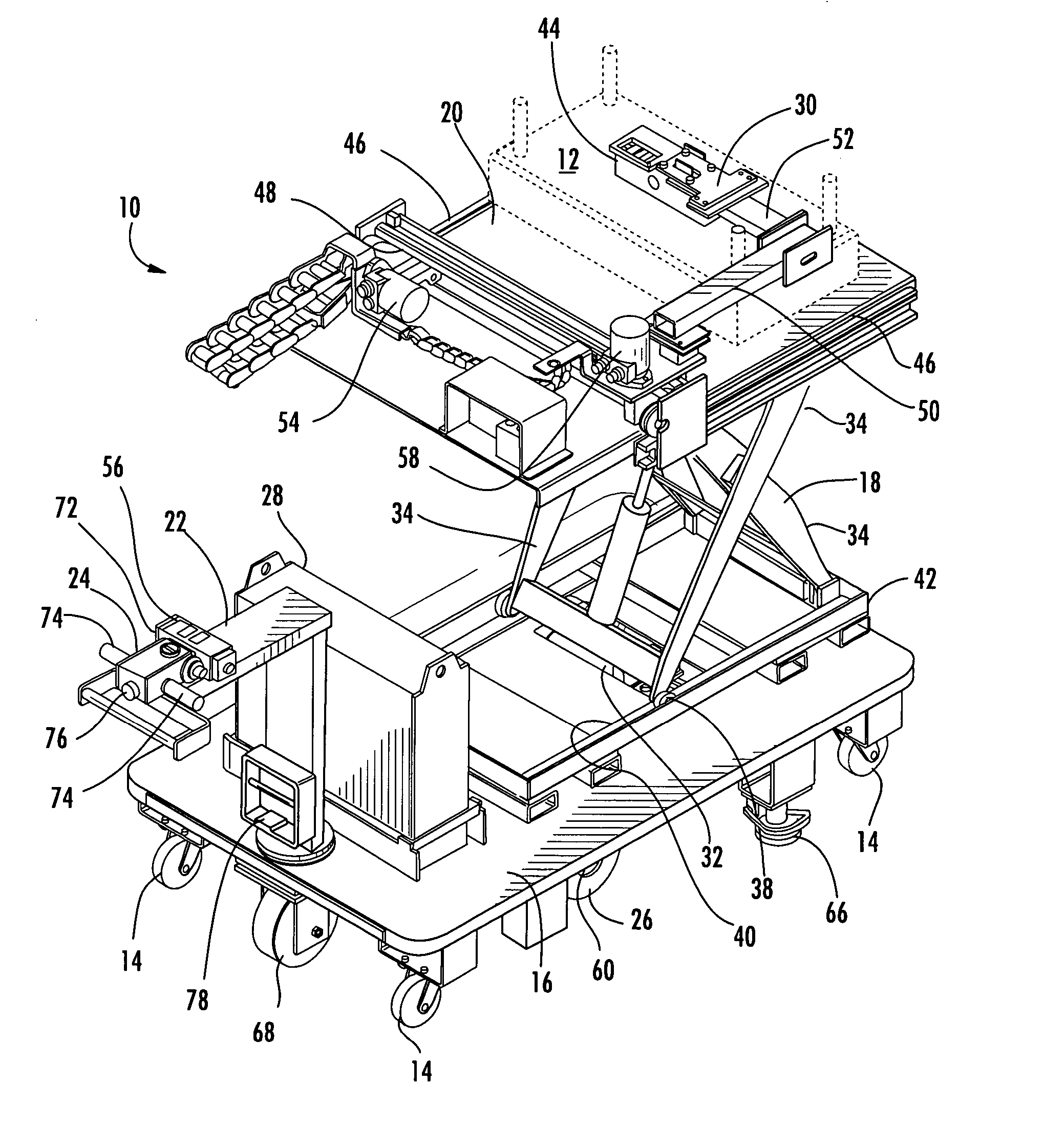
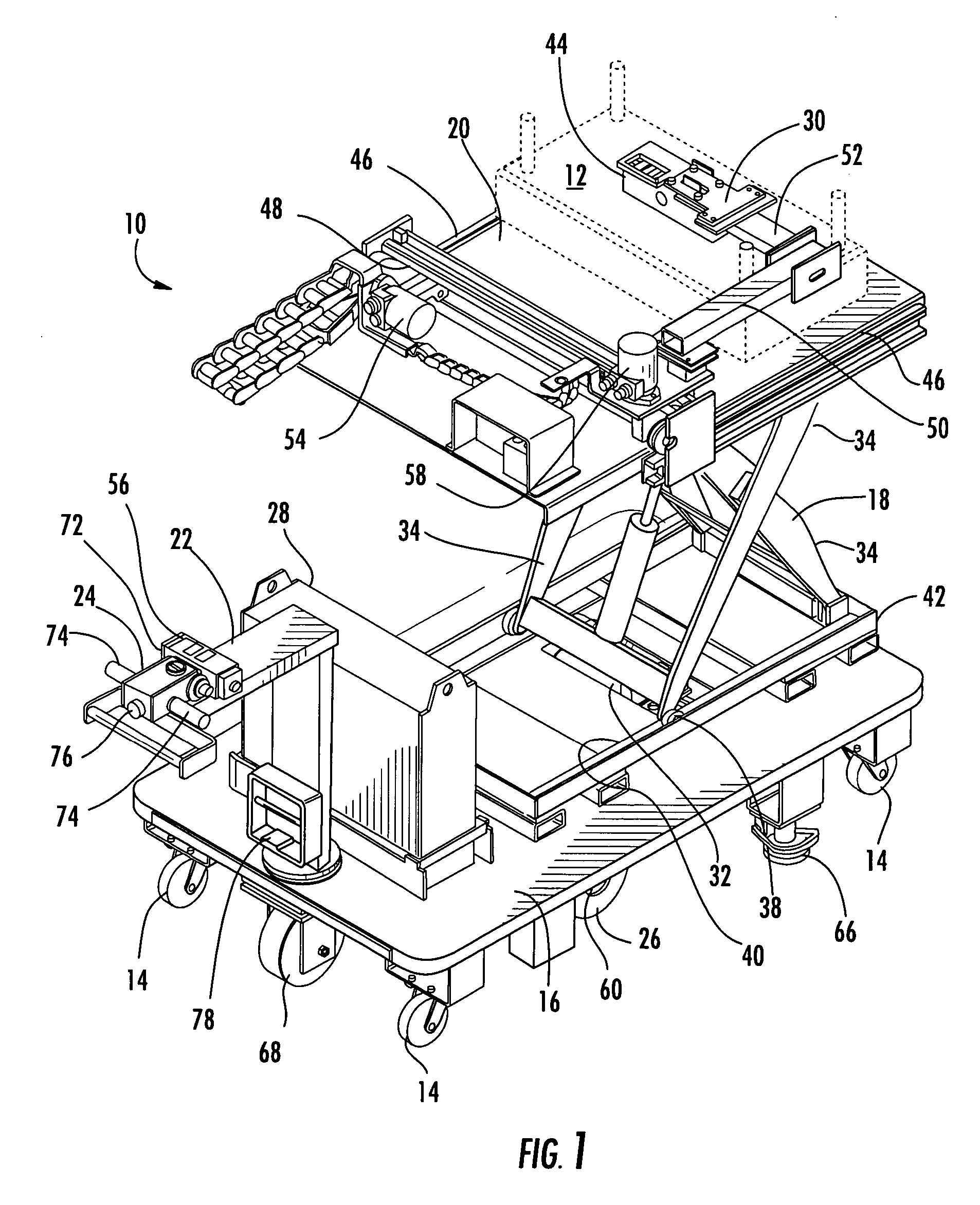
[0032] The transfer mechanism 30 of FIGS. 1-5 includes a first arm 50 that extends longitudinally from an end that is mechanically connected to the second electric motor 58. A second arm 52 extends laterally approximately half the length of the second linear rail 48 from an end of the first arm opposite the end that is mechanically connected to the second electric motor 58. Further embodiments of the present invention include a first arm 150 that extends longitudinally and a second arm 152 that extends laterally as illustrated in FIGS. 6-10, and still further embodiments of the present invention include arms that extend at an angle to the longitudinal or lateral directions or include three or more arms or a unitary curved arm or the like. Referring again to FIGS. 1-5, the first arm 50 and second arm 52 define selectively adjustable attachments such that the operator can reconfigure the first and second arms in any sequence, such as the second arm connected to the second motor and th...

third embodiment

[0052]FIG. 11 illustrates the present invention, in which the cart transfer mechanism 230 of the cart 210 includes a suction device 244. The suction device 244 is capable of selectively engaging a die 212 in response to the control assembly 224, or more particularly, in response to the controller 256. The operator, using the controller 256, moves the suction device 244 longitudinally and laterally, using the first motor 254 and second motor 258, respectively, until the suction device is substantially positioned above the die 212 and is contacting the die a sufficient amount to create a vacuum. The operator, again using the controller 256, activates the suction device 244 which couples to the die 212 and may deflect the suction device downward to fully contact the top surface of the die. Preferably the top surface of the die 212 is substantially free of any connectors, hoses, or the like and is substantially flat so that an air-tight suction may be formed between the suction device a...


PUM

PropertyMeasurementUnit
Lengthaaaaaaaaaa
Weightaaaaaaaaaa
Forceaaaaaaaaaa

Abstract

There is provided a cart for transporting dies, molds, and similar objects. The cart includes a lift mechanism for raising and lowering a support surface to the height of the surface onto which or from which the die will be moved. The support surface includes a transfer mechanism for coupling to the die, either with an electromagnet or a suction device, to thereby slide the die as desired without damaging critical components on the exterior of the die. The cart also includes a motorized drive wheel assembly which provides a drive force in a forward or backward direction to assist the operator in moving a die that has been transferred onto the cart. The cart is powered by one or more rechargeable batteries. The cart enables a single operator to safely and conveniently remove, insert, and transport dies or other similar objects.

Description

CROSS REFERENCE TO RELATED APPLICATION [0001] The present application claims priority pursuant to 35 U.S.C. 119(e) to U.S. Provisional Application Ser. No. 60 / 679,059, filed May 9, 2005 and U.S. Provisional Application Ser. No. 60 / 644,900, filed Jan. 19, 2005.BACKGROUND OF THE INVENTION [0002] 1. Field of the Invention [0003] The present invention is related to carts for material handling, and more particularly, to carts that assist in transporting dies or molds. [0004] 2. Description of Related Art [0005] Dies or molds are used in various industries for the blow-molding or injection-molding of components, such as plastic components. Dies typically comprise two or more blocks of alloy steel or other suitable metal or material that are connected such that one block may be moved in at least one direction, typically vertically, relative to the other block. The mating surfaces of the blocks define a die cavity with contours of the one or more components that are molded within the die. D...

Claims


Application Information

Patent Timeline
IPC IPC(8): B23Q3/155
CPCB29C31/006B29C33/32B30B15/028Y10T483/1729B66F9/181B66F9/182Y10T483/10B62B3/10
Inventor SPRINGSTON, ERIC D.PRATT, JOHN R.WILLIAMS, DALE A.
Owner MULTI SHIFTER
Why Eureka
Try Eureka