Gage side or field side top-of-real plus gage corner lubrication system

Active Publication Date: 2006-07-27
TRANERGY CORP
View PDF7 Cites 14 Cited by
  • Summary
  • Abstract
  • Description
  • Claims
  • Application Information

AI Technical Summary

Benefits of technology

[0009] Each nozzle holder block houses the nozzles and check valves for the different jets. Each nozzle directs the fluid jet in different directions on each rail in this way. The drawings show only two jets, one in the forward direction towards the approaching train and the other in the backward direction in which the train is moving. However, there can be many more jets if desired. The shot duration is determined by the amount of fluid to be applied to the rail. If the train is approaching at a very fast speed, the wheels may sometime intercept the jets fired towards it. However, the jets fired in the opposite direction (direction of train) will still fall on the rail. A computer controls the frequency and duration of each shot. The software is based on timing the approaching wheels such that at the instant the shot is fired, the nozzle holders are located intermediate the trucks of the car. However, this does not have to be so. A certain minimum number of shots (several) may need to be fired based on experience with the degree of lubrication needed. The logic for timing the shots is such that lubricant shots are not fired on the rail before passage of locomotive wheels. When three axles pass over the sensor, equal time apart or when time duration is longer between axles than those of cars, it is identified as a locomotive wheel and the lube shot on the rail is not fired. By this approach the locomotives and possibly the first car will pass before the system starts lubricating the rail. An environmentally clean top-of-rail curve lubricant, which flows smoothly under different temperature conditions, is used for this purpose. An enclosure or box located on the track wayside contains the computer, fluid and hydraulic and electrical control systems. Hoses from the box transmit fluid to each of the nozzle holders. The fluid is pressurized by a finite displacement pump or another system which can deliver controlled quantities of the fluid shot. Electrical connections are provided from the box to the two sensors mounted on the rail on either side of the nozzle holder block. AC power can be used for the box where available. If not, DC power from a battery, which is charged by solar cells, is used.

Problems solved by technology

Top-of-rail lubrication can be done by this method when it is not possible to mount the blocks on the gage side for some reason.

Method used


Image

  • Gage side or field side top-of-real plus gage corner lubrication system
  • Gage side or field side top-of-real plus gage corner lubrication system
  • Gage side or field side top-of-real plus gage corner lubrication system

Examples


Embodiment Construction

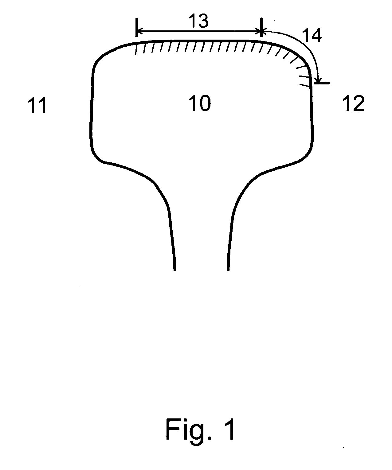
[0019]FIG. 1 illustrates the zone of wheel-rail contact on a railhead that defines the regions of the rail requiring lubrication on a curve. The railhead 10 can be either the high rail or the low rail. The field side of the rail is at 11 and the gage side is indicated at 12. The contact area of the wheel on the high rail (for most train operating conditions) is marked with hashed lines. This area can be broken into two regions 13 and 14. Region 13 is essentially the top of the rail and region 14 is the gage corner. The two regions collectively will be referred to herein as the contact area. The wheel tread contacts the rail in different parts of region 13 and the wheel flange contacts the rail in parts or all of region 14. Friction work on the high rail is done by the wheel in both regions 13 and 14. For the low rail a mirror reflection on the right can be considered. However, the contact of wheel and low rail generally lies only in region 13. Only for very low train speeds (below e...


PUM


Abstract

A rail lubricator for a railroad rail has a nozzle adjacent to the rail and attached thereto. The nozzle has a discharge orifice disposed beneath the top surface of the rail. The orifice is aimed generally longitudinally of the rail with the aiming including an upward component and a lateral component toward the centerline of the rail. Jets of lubricant project upwardly from the nozzle, arch above the top surface of the rail, and then fall onto the top surface and gage corner of the rail. This lubricates the top of a rail using an optimum amount of lubricant on the optimum area of the railhead. The lubricant is applied when the nozzles are spanned by a car.

Description

BACKGROUND OF THE INVENTION [0001] This invention concerns a method and apparatus for applying lubricant to railroad rails. Rail lubrication on curves has been considered important for a long time, primarily for the purpose of reducing wear on wheels and rails. Traditionally, lubricating devices in railroad yards used long bars mounted on the gage side of the rail. Grease oozes out of small holes in the bar in response to the pressure of a passing train, and is picked up by the flanges of wheels and spread over the rail gage corner. These grease lubricators are difficult to control, leading to excessive grease being applied and accumulated near the applicator. It is messy, manpower intensive, hazardous to track crews, and expensive to maintain. In spite of such lubrication, high lateral forces continue to develop on the rail. This produces significant damage to track components such as spikes, ties, tie plates, ballast and the overall structure of the track. [0002] A new approach ca...

Claims


Application Information

Patent Timeline
Patent Type & Authority Applications(United States)
IPC IPC(8): B61K3/00
CPCB61K3/00
Inventor KUMAR, SUDHIR
Owner TRANERGY CORP
Why Eureka
Try Eureka