Rubber bushing

Inactive Publication Date: 2006-07-27
ARVINMERITOR TECH
View PDF19 Cites 23 Cited by
  • Summary
  • Abstract
  • Description
  • Claims
  • Application Information

AI Technical Summary

Benefits of technology

[0008] Preferably, the first and second bushings are fixed to the central body in an interference fit. The washer is supported on the pin intermediate the first and second bushings. The washer is rigidly held in place by the first and s

Problems solved by technology

This traditional configuration is expensive and often does not provide sufficient conical compliance during ve

Method used


Image

  • Rubber bushing
  • Rubber bushing
  • Rubber bushing

Examples


Embodiment Construction

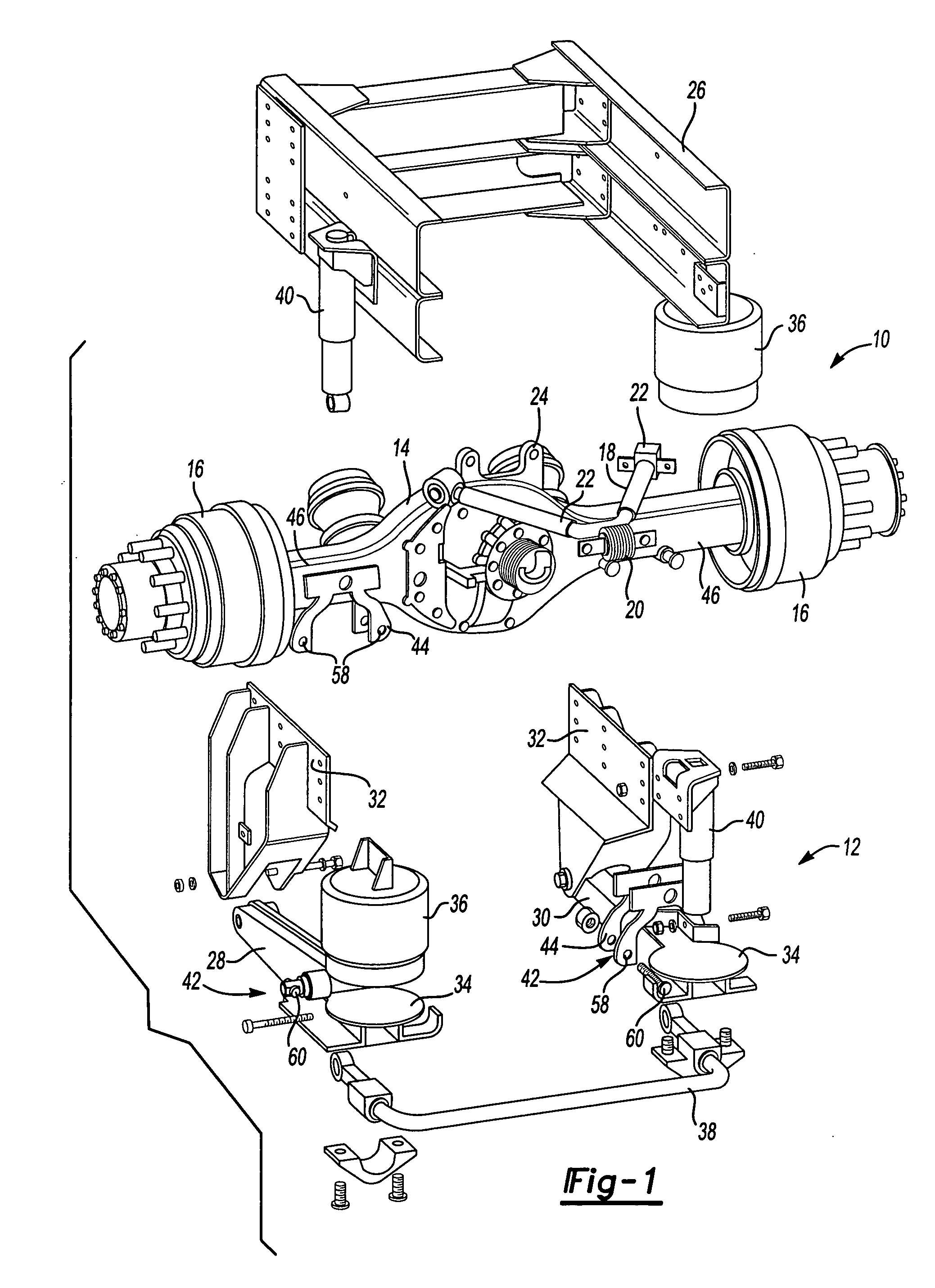
[0013] An axle assembly 10 with a suspension system 12 is shown in FIG. 1. The axle assembly 10 includes an axle housing 14 that extends between a pair of wheel ends 16. The suspension system 12 includes a V-rod 18 with a center pivot 20 and a pair of legs 22 that extend outwardly from the center pivot 20. The center pivot 20 is mounted at a center portion 24 of the axle housing 14 and each leg of the pair of legs 22 is mounted to a vehicle frame 26 as known.

[0014] The suspension system 12 also includes first 28 and second 30 trailing arms that are mounted to suspension hanger brackets 32 at one end, and which include spring seats 34 for supporting air springs 36. A stabilizer bar assembly 38 extends laterally between the first 28 and second 30 trailing arms. The suspension hanger brackets 32 are mounted to the vehicle frame 26. Shock absorbers 40 are also mounted between the vehicle frame 26 and the first 28 and second 30 trailing arms.

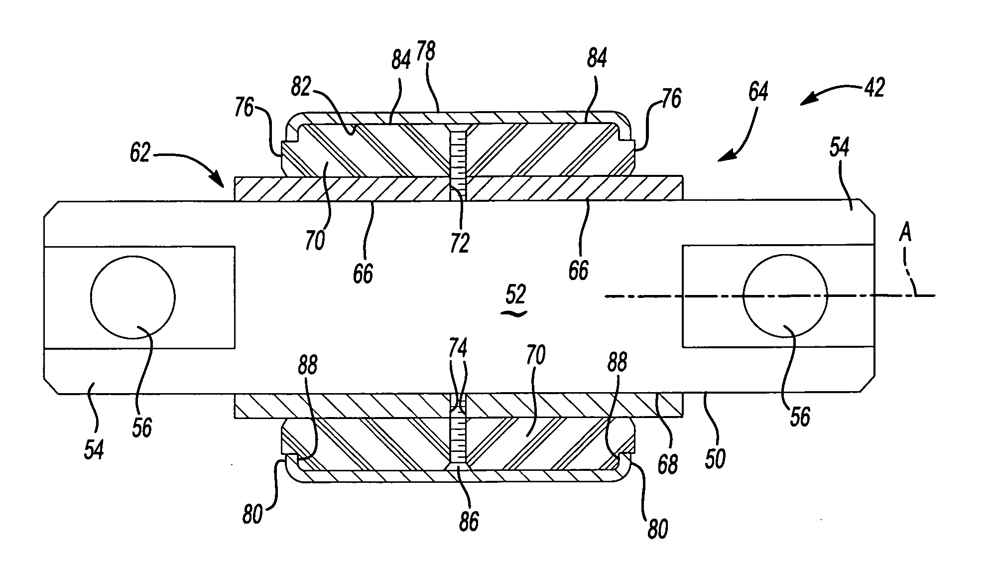
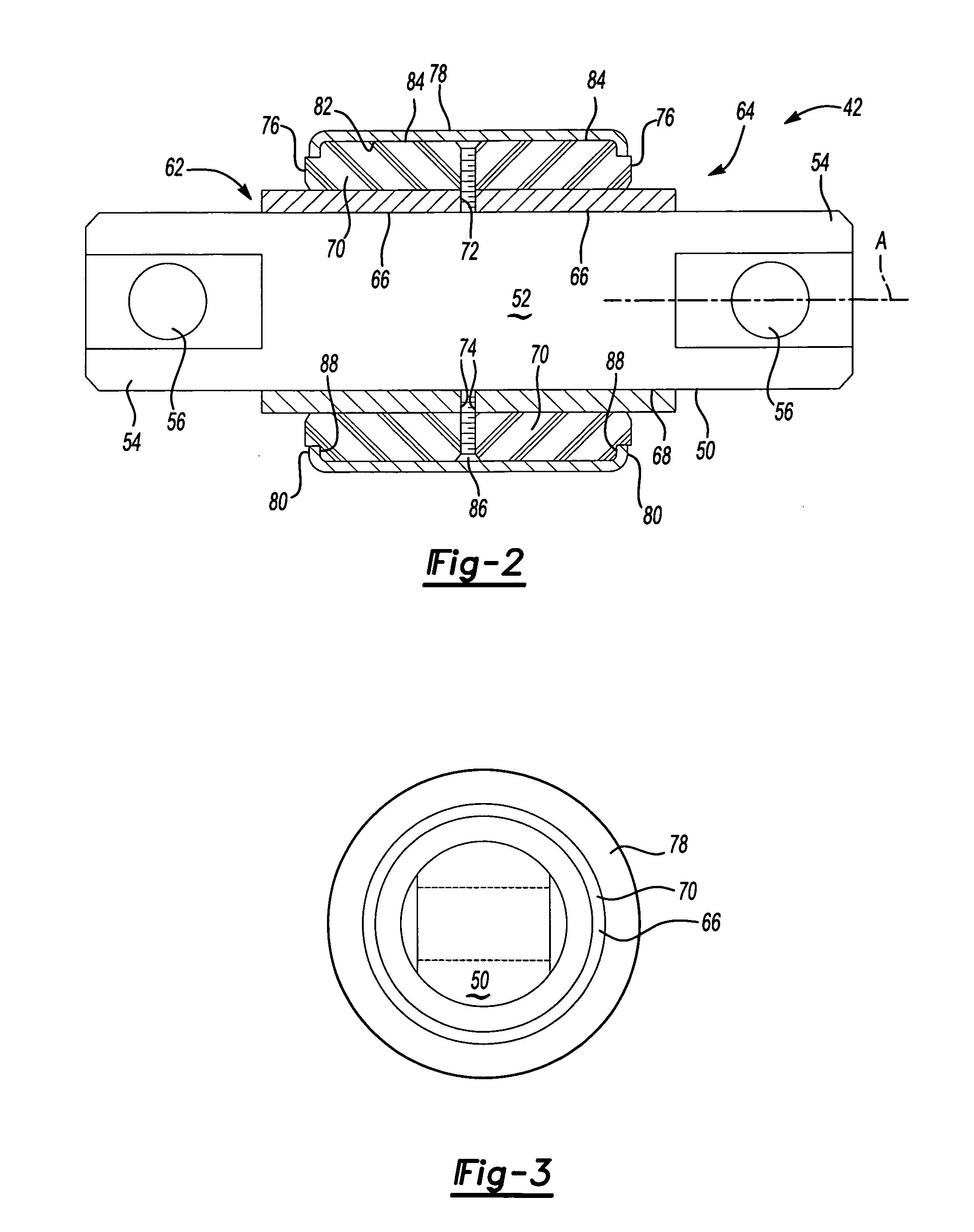
[0015] A bushing assembly 42 is supported on...


PUM


Abstract

A bushing assembly for a vehicle suspension system includes first and second bushing components that are fixed to a central pin. The pin is supported on a suspension component and includes pin ends that are mounted to an axle housing component. A washer is supported on the pin between the first and second bushings and abuts against inboard edges of the first and second bushings. An outer retaining tube surrounds the first and second bushings and the washer. The outer retaining tube includes opposing deformed end portions that directly engage outboard edges of the first and second bushings to form axial load carrying surfaces for the first and said second bushings.

Description

TECHNICAL FIELD [0001] The subject invention relates to a bushing assembly for a vehicle suspension system that includes a pair of bushing members separated by a washer and an outer retaining sleeve that surrounds the pair of bushing members and provides axial load carrying surfaces for the bushing assembly. BACKGROUND OF THE INVENTION [0002] Vehicle suspension systems include bushing assemblies that are mounted between a suspension beam component and an axle housing. Typically, each bushing assembly includes an inner sleeve, an outer sleeve, and a piece of urethane or rubber that is positioned between the inner and outer sleeves. The inner sleeve is supported on a pin with the outer sleeve surrounding an outer circumferential surface of the rubber sleeve. [0003] In order to accommodate axial loading, the bushing assembly has traditionally required a large single piece of rubber or urethane between the inner and outer sleeves. This traditional configuration is expensive and often do...

Claims


Application Information

Patent Timeline
IPC IPC(8): F16F7/00
CPCB60G7/02B60G11/64B60G2200/315B60G2202/135B60G2202/152B60G2204/143B60G2204/41B60G2204/44F16F1/3842
Inventor KIDDLE, ROBERT MICHAEL
Owner ARVINMERITOR TECH
Why Eureka
Try Eureka