Attenuated-total-reflection measurement apparatus

a measurement apparatus and total reflection technology, applied in the direction of optical radiation measurement, instruments, spectrophotometry/monochromators, etc., can solve the disadvantage of reattaching the prism at the position where the prism and sample were in contact, and difficult to carry out mapping measurement with a spatial resolution below, etc., to achieve high-speed, high-precision two-dimensional mapping measurement and efficiently radiated light

Active Publication Date: 2006-07-27
JASCO CORP
View PDF3 Cites 26 Cited by
  • Summary
  • Abstract
  • Description
  • Claims
  • Application Information

AI Technical Summary

Benefits of technology

[0010] The present invention has been conceived in light of the problems described above, and an object thereof is to provide an attenuated-total-reflection measurement apparatus that can perform high-speed, high-resolution two-dimensional mapping measurement, even when using a single-element detector or a linear-array detector.
[0018] According to the present invention, a detection-side scanning mirror whose reflecting surface can be changed in orientation is provided, and a measurement site in the contact surface between a sample and an ATR prism is changed by changing the orientation of this reflecting surface. Therefore, it is possible to perform high-speed, high-precision two-dimensional mapping measurement even when using a single-element detector or a one-dimensional multi-element detector.
[0019] Furthermore, according to the present invention, an irradiation-side scanning mirror whose reflecting surface can be changed in orientation is provided, and an irradiation site in the contact surface between a sample and an ATR prism is changed by changing the orientation of this reflecting surface. Therefore, a measurement site can be efficiently radiated with light.

Problems solved by technology

This results in problems, such as positional error of the prism, contamination at the contact surface of the prism when attaching it to the sample, and so forth, which are undesirable for high-speed, high-precision mapping measurement.
In the measurement described above, because light from the central part of the contact surface is received by the single-element detector, it is difficult to carry out mapping measurement with a spatial resolution below the size of the contact surface between the ATR prism and the sample (normally, the diameter of this region is about 100 μm).
However, it is difficult to minutely change the position of the prism, and in addition, reattaching the prism at the position where the prism and sample were in contact is disadvantageous from the point of view of measurement.
However, a two-dimensional multi-element detector such as the focal plane detector array (FPA) disclosed in U.S. Pat. No. 6,141,100 has the following problems: (1) the cost is high; (2) because signals are read out from the elements in a serial fashion, it takes some time to complete acquisition of all data; (3) the measurement wavelength range is limited; and (4) defects occur in some of the elements in the light-receiving surface when fabricating the photodetector.

Method used


Image

  • Attenuated-total-reflection measurement apparatus
  • Attenuated-total-reflection measurement apparatus
  • Attenuated-total-reflection measurement apparatus

Examples


Embodiment Construction

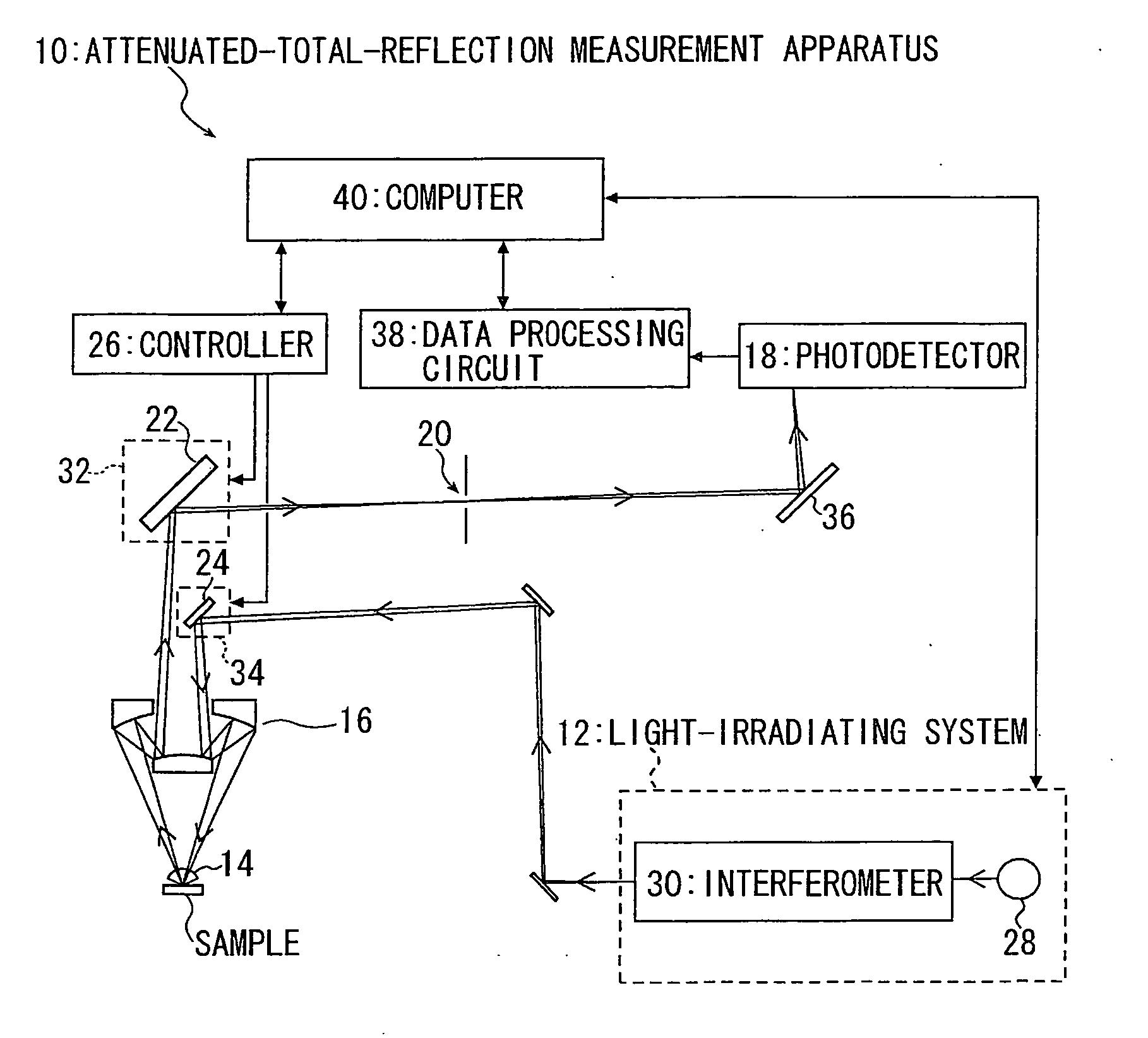
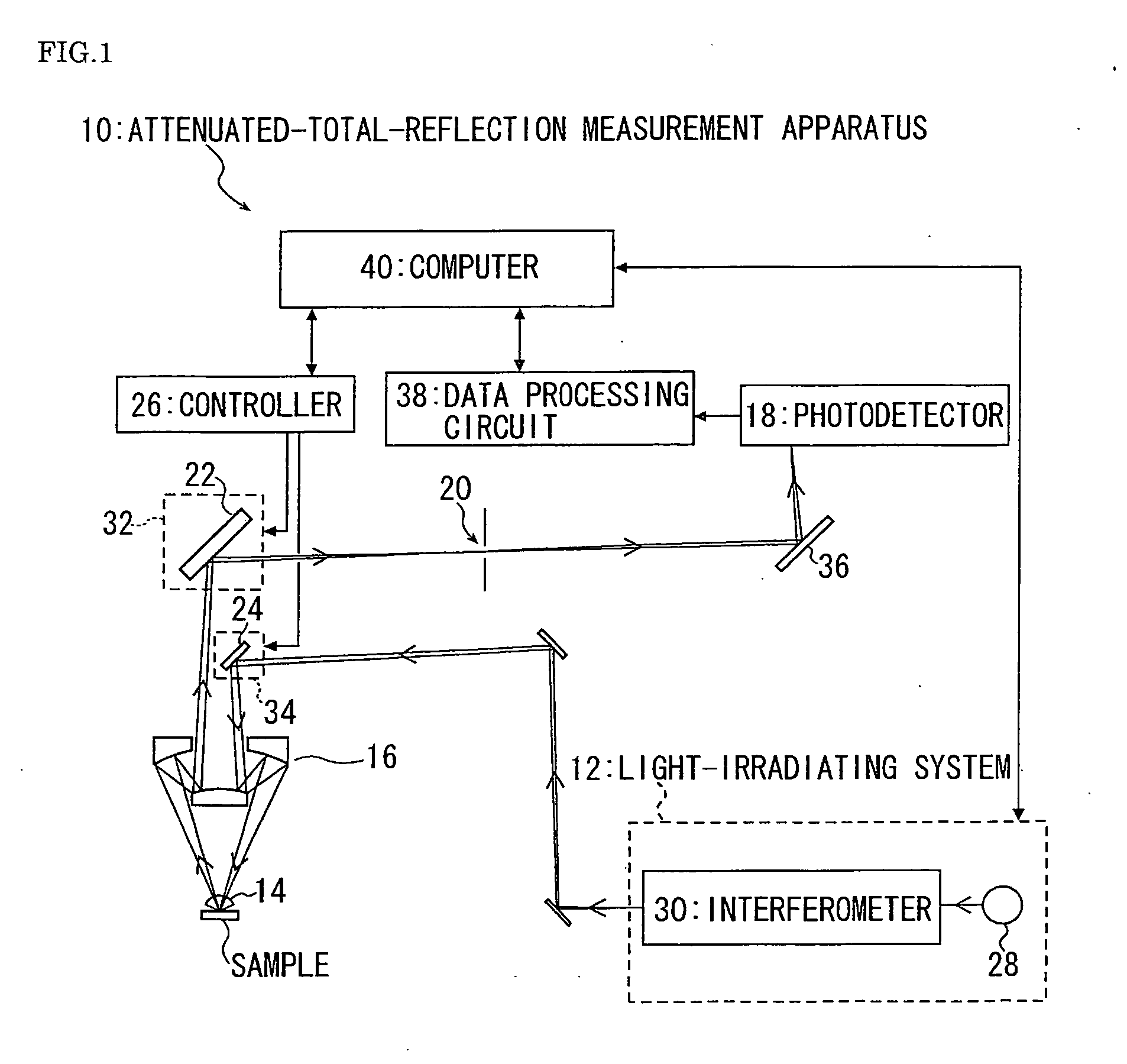
[0028] A preferred embodiment of the present invention will be described below with reference to the drawings. FIG. 1 is an outlined diagram of an attenuated-total-reflection measurement apparatus 10 according to the embodiment of the present invention. The attenuated-total-reflection measurement apparatus 10 of this embodiment includes a light-irradiating system 12; an ATR prism 14 that contacts a sample surface; an objective mirror (microscope optical system) 16 for collecting light onto the contact surface between the sample and the ATR prism 14 and for collecting light reflected from the contact surface; a photodetector (photodetector system) 18 for detecting the reflected light; an aperture 20 for restricting the light traveling towards the photodetector 18 to light emanating from a specific position in the contact surface; a detection-side scanning mirror 22 positioned in the light path extending from the ATR prism 14 to the aperture 20; and an irradiation-side scanning mirror...


PUM

PropertyMeasurementUnit
diameteraaaaaaaaaa
incident angleaaaaaaaaaa
critical angleaaaaaaaaaa

Abstract

An attenuated-total-reflection measurement apparatus 10 of the present invention collects light onto a contact surface between a sample and an ATR prim 14 at an incident angle greater than or equal to a critical angle and measures total-reflection light from the contact surface. The attenuated-total-reflection measurement apparatus 10 comprises: a light-irradiating system 12 for emitting the light which is collected onto the contact surface; a photodetector 18 for detecting the total-reflection light from the contact surface; an aperture 20 for restricting the light which the photodetector 18 detects to only light from a specific measurement site in the contact surface; and a detection-side scanning mirror 22 provided in a light path extending from the ATR prism 14 to the aperture 20. The detection-side scanning mirror 22 is configured to allow the orientation of a reflecting surface thereof to be changed. And the measurement site in the contact surface, which is to be measured with the photodetector 18, is changed by moving the reflecting surface of the detection-side scanning mirror 22 with respect to the total-reflection light from the contact surface, to perform mapping measurement in the contact surface.

Description

RELATED APPLICATIONS [0001] This application claims priority to the Japanese Patent Application 2005-16439 dated on Jan. 25, 2005 and is hereby incorporated with reference for all purposes. BACKGOUND OF THE INVENTION [0002] 1. Field of the Invention [0003] The present invention relates to attenuated-total-reflection measurement apparatuses, and more particularly, to an improved mapping mechanism thereof. [0004] 2. Description of the Related Art [0005] Attenuated total reflection (ATR) is a measurement technique in which an ATR prism, which is a medium having a high refractive index, is placed in close contact with the surface of a sample to be measured. That is, under total-reflection conditions at the interface between the sample and the prism, light is incident on the surface of the sample via the ATR prism, and reflected light is measured. During total reflection, the light slightly penetrates into the sample surface, and some absorption occurs in a vicinity of the sample surface...

Claims


Application Information

Patent Timeline
Patent Type & Authority Applications(United States)
IPC IPC(8): G01J3/00G01N21/27G01N21/552
CPCG01J3/02G01J3/021G01N21/552
Inventor KOSHOUBU, JUNSOGA, NORIAKI
Owner JASCO CORP
Why Eureka
Try Eureka