
Pigtail light string

Inactive Publication Date: 2006-07-27
LAI WIN CHING
View PDF3 Cites 33 Cited by
  • Summary
  • Abstract
  • Description
  • Claims
  • Application Information

AI Technical Summary

Benefits of technology

[0004] The present invention has been made to overcome the above-mentioned drawback of conventional light strings. The primary object of the present invention is to provide a pigtail light string compatible with conventional light string to provide a wider range of light change patterns so that the conventional light strings can extends their lifespan. The structure of the present invention includes a plurality of light modules, and each module includes LEDs of two colors. Because each module can display the all-same, all-different, or sequential color change, so that the overall string will display a great variety of color change patterns.
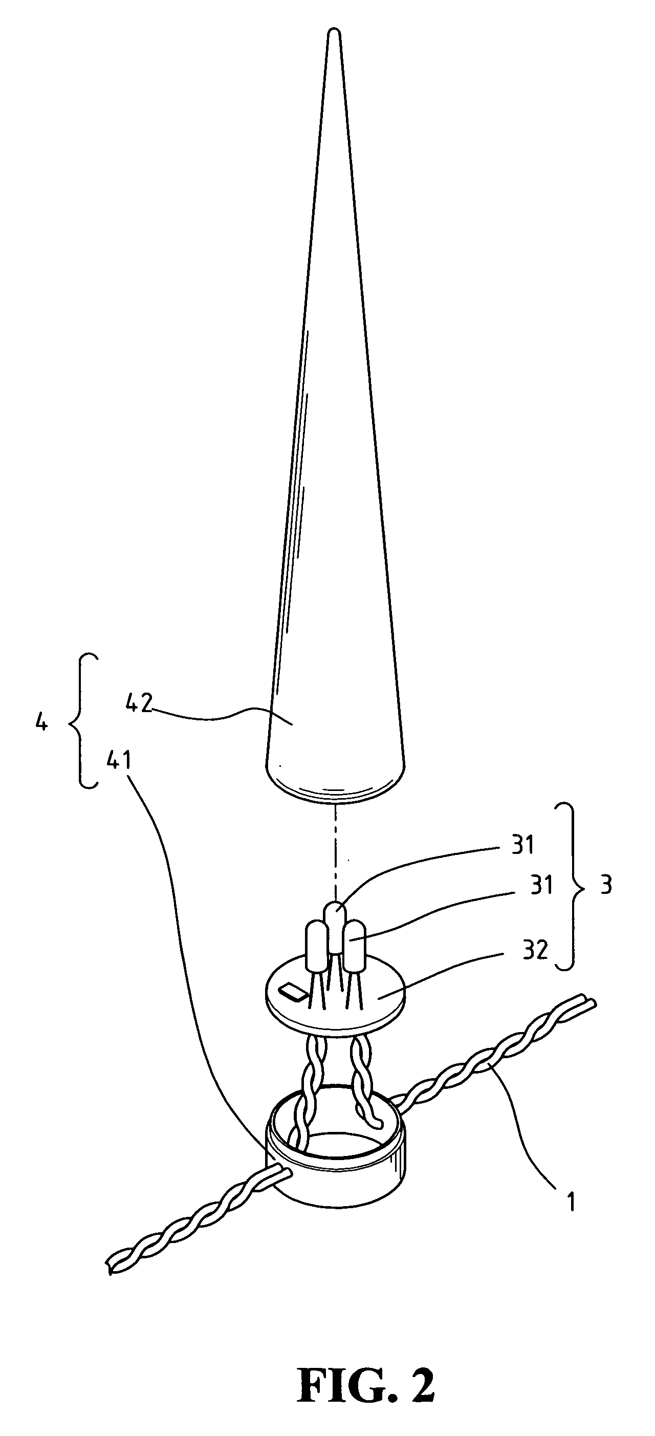
[0005] Another object of the present invention is to provide a pigtail tree-top light by using a single or a plurality of light modules, combined with the decorative shells, such as a star of the top of a Christmas tree. This can be used to replace the conventional tree-top light. So, instead of plugging in the electricity plug directly, the present invention is more convenient by plugging in the socket of a conventional light string.
[0006] Yet another object of the present invention is to provide a light string with more styles. By putting different styles of decorative shells to enclose the light modules, such as ice cone, or sphere, the light modules of the present invention can have same or different style of decorative shells. By changing the color of the enclosed light module, the various decorative shells of the pigtail light string can display a wide range of visual effects.

Problems solved by technology

In addition, most conventional light strings have a limited range of light change patterns, such as blinking, round-robin style of light color change, and so on.
With the advance of lighting technologies in the last decade, the conventional light strings are losing their attraction.

Method used


Image

  • Pigtail light string
  • Pigtail light string
  • Pigtail light string

Examples


Embodiment Construction

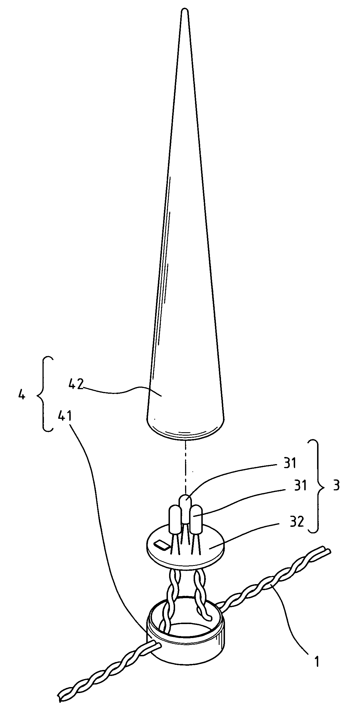
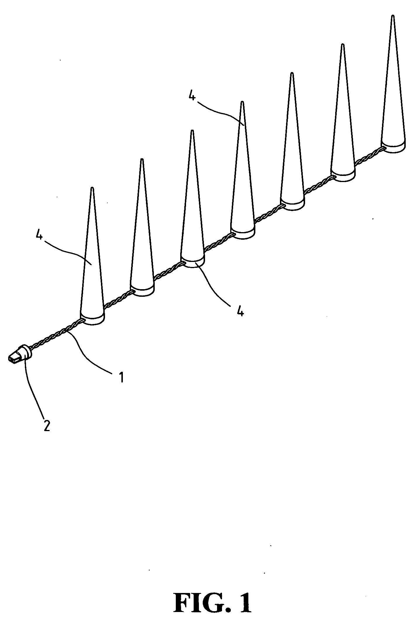
[0015] As shown in FIG. 1 and FIG. 2, the pigtail light string of the present invention includes a power conductive line 1, power connector 2, a plurality of light modules 3, and a plurality of decorative shells 4. Power connector 2 is attached to one end of power conductive line I for electrical connection. Light modules 3, each enclosed in a decorative shell, are installed on power conductive line in parallel.

[0016] Power conductive line I are installed with two or more light modules 3 in parallel. Power connector 2 has the shape of the base of a conventional light bulb used in a conventional light string 5, so that it can be plugged into a socket 51 for receiving a conventional light bulb on conventional light string 5, as shown in FIG. 3. The shape of power connector 2 is not limited to the embodiment shown in FIG. 3. The base of any light bulb in a conventional light string can be used as the shape for power connector 2. Therefore, power connector 2 can be made in any shape to...


PUM


Abstract

A pigtail light string is provided for using in a conventional light string. The pigtail light string includes a conductive line connecting at least two or more light modules in parallel. The light modules includes LEDs of at least two colors and a control circuit board for generating different lighting patterns, such as colors, brightness, duration, and so on. Each light module is enclosed in a translucent decorative shell. One end of the conductive line is attached to a power plug for plugging into a socket of a light bulb on a conventional light string. The shape of the power plug is that of the base of a bulb used in a conventional light string so that the pigtail light string can be plugged into a socket for receiving a bulb on a conventional light string. When used in combination with conventional light strings, the pigtail light string provides a wider range of light change patterns as well as various decorative styles.

Description

FIELD OF THE INVENTION [0001] The present invention generally relates to a light string, and more specifically to a pigtail light string having more change patterns and drawing power from a light bulb socket of a conventional light string. BACKGROUND OF THE INVENTION [0002] The conventional light strings are mostly made of tungsten and stringed in a serial manner. After a long period of use, the temperature of the light bulbs will arise. When one of the light bulbs burned out, the entire light string will cease to function. In addition, most conventional light strings have a limited range of light change patterns, such as blinking, round-robin style of light color change, and so on. With the advance of lighting technologies in the last decade, the conventional light strings are losing their attraction. A newer, more attractive and versatile light string is in demand. [0003] A new product can gain more market acceptance if the new product is compatible with the older competitive prod...

Claims


Application Information

Patent Timeline
IPC IPC(8): F21V9/00
CPCF21S4/001F21V3/00F21S10/023F21Y2101/02F21Y2113/005F21W2121/006F21S4/10F21Y2115/10F21Y2113/13
Inventor LAI, WIN-CHING
Owner LAI WIN CHING
Learn More